¶ 1. Tools:
- S2.0 Allen key
- S2.5 Allen key
¶ 2. Disassembly steps:
¶ Step 1: Turn off the printer
Before replacement, please turn off the printer and disconnect the power supply to ensure safe operation.
¶ Step 2: Turn off ACE Pro
Unplug the ACE Pro signal cable and power cable, then remove the Teflon tube.

¶ Step 3: Disassemble the ACE Pro housing
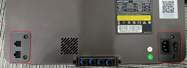
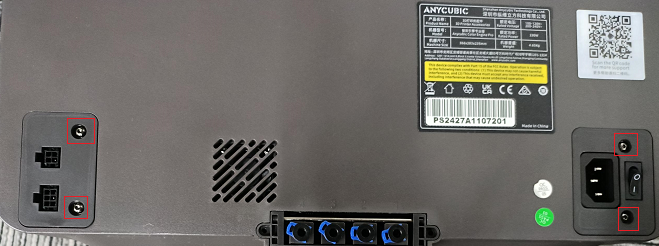
1. Remove the four screws fastening the ACE Pro signal input board and power cover using the S2.0 Allen key.
2. Tear off the foot pads and use an S2.5 Allen key to unscrew the six screws that secure the inner shell of ACE Pro.

¶ Step 4: Separate the ACE Pro inner shell
Use an S2.5 Allen key to unscrew the two screws that secure the multi-color cover, and then separate the ACE Pro inner and outer shells.


¶ Step 5: Remove the air duct cover
1. Remove the NFC signal cables on both sides.
2. Use an S2.0 Allen Key to unscrew the two screws that secure the NTC signal cable.
3. Use an S2.0 Allen key to unscrew the eight fixing screws on the air duct cover plates on both sides.

¶ Step 6: Replace the PTC heater
1. Remove the heater cable from the slot.

2. Replace the PTC heating sheet, install the two PTC heating sheet probes into the multi-color inner shell slots, and apply thermal conductive silicone on the surface, paying attention to the installation position distinction.

3.Then install the PTC heating sheet into the multi-color inner shell slot, and then insert the PTC wire into the slot.

¶ 3. Installation steps:
¶ Step 1: Install the air duct cover
1. Use an S2.0 Allen key to install and fix the air duct covers on both sides.
2. Install the NTC signal line and use an S2.0 Allen key to fix the two screws of the NTC signal line.
3. Connect the NFC signal line wiring plugs on both sides back.

¶ Step 2: Install the ACE Pro inner shell
1. Replace the inner shell, install the baffle, use an S2.0 Allen key to tighten the screws that fix the baffle, and then stick the sealing strip.

2. Install the multi-color panel, and then use the S2.5 Allen key to tighten the two screws that secure the multi-color panel.
¶ Step 3: Fix the ACE Pro housing
1. Use an S2.0 Allen key to tighten the two screws that fix the cover.

2. Use an S2.5 Allen key to tighten the screws that secure the housing, then glue on the foot pads.
¶ Step 4: Connect ACE Pro and printer
Install the Teflon tube, then plug the ACE Pro signal cable and power cable back into the interface.