¶ 1. Tools:
S2.0 Allen key
S2.5 Allen key
S3.0 Allen key
¶ 2. Disassembly Steps:
¶ Step 1: Power Off the Machine
Before starting the replacement of the Y-axis motor, ensure you have a relatively spacious worktable or desktop for disassembly. It is crucial to turn off the machine and disconnect the power to ensure your safety during the operation.
¶ Step 2: Loosen the Belts
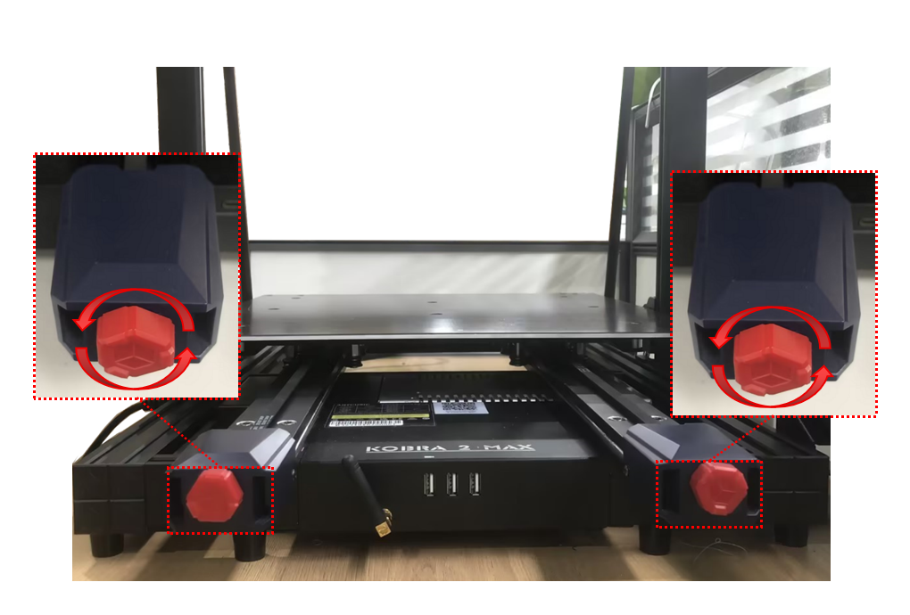
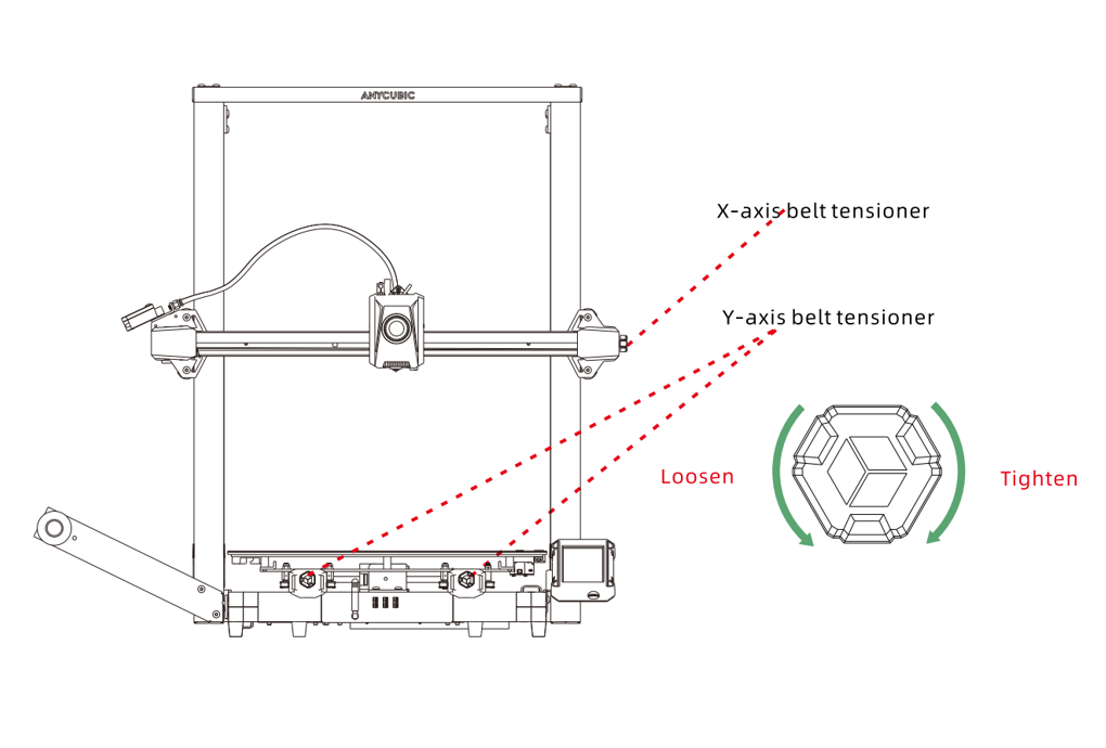
Rotate the red knobs counterclockwise on the two belt tensioners of the Y-axis to facilitate the subsequent removal of the synchronous wheels from the belts.
¶ Step 3: Disconnect Cables
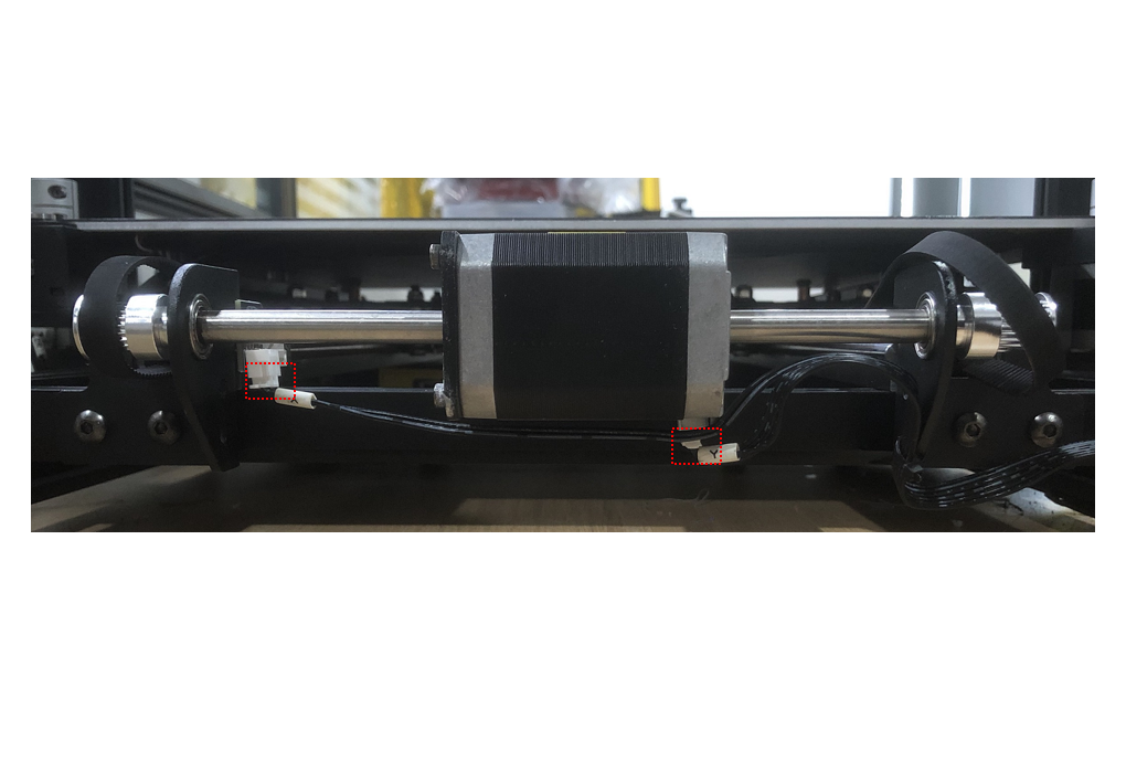
Refer to the diagram and unplug the Y-axis motor cable and the Y-axis limit switch cable to facilitate the motor removal and sheet metal movement.
¶ Step 4: Remove Synchronous Wheels
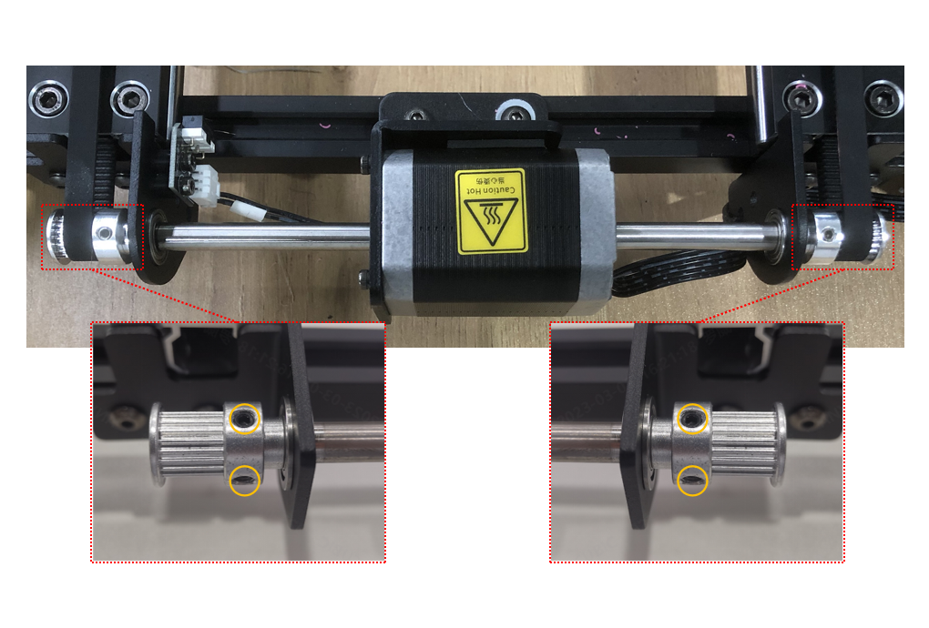
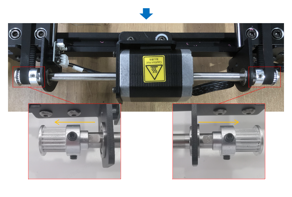
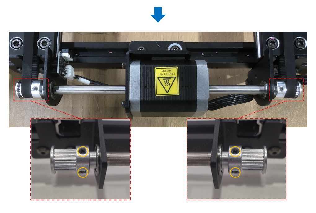
Use the S2.0 Allen key to loosen the 2 set screws on each side of the motor, then remove the synchronous Wheels from the motor shaft. If the synchronous wheels are difficult to remove, you could rotate the red knobs on the two belt tensioners counterclockwise to loosen the synchronous belts.
¶ Step 5: Remove Right Fixed Sheet Metal
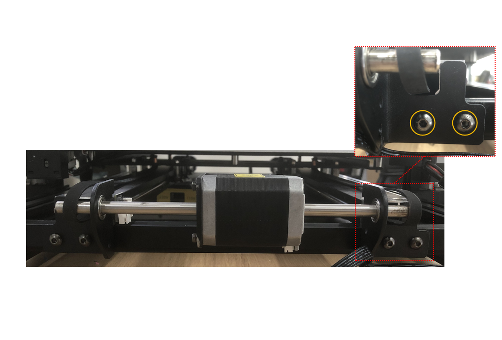
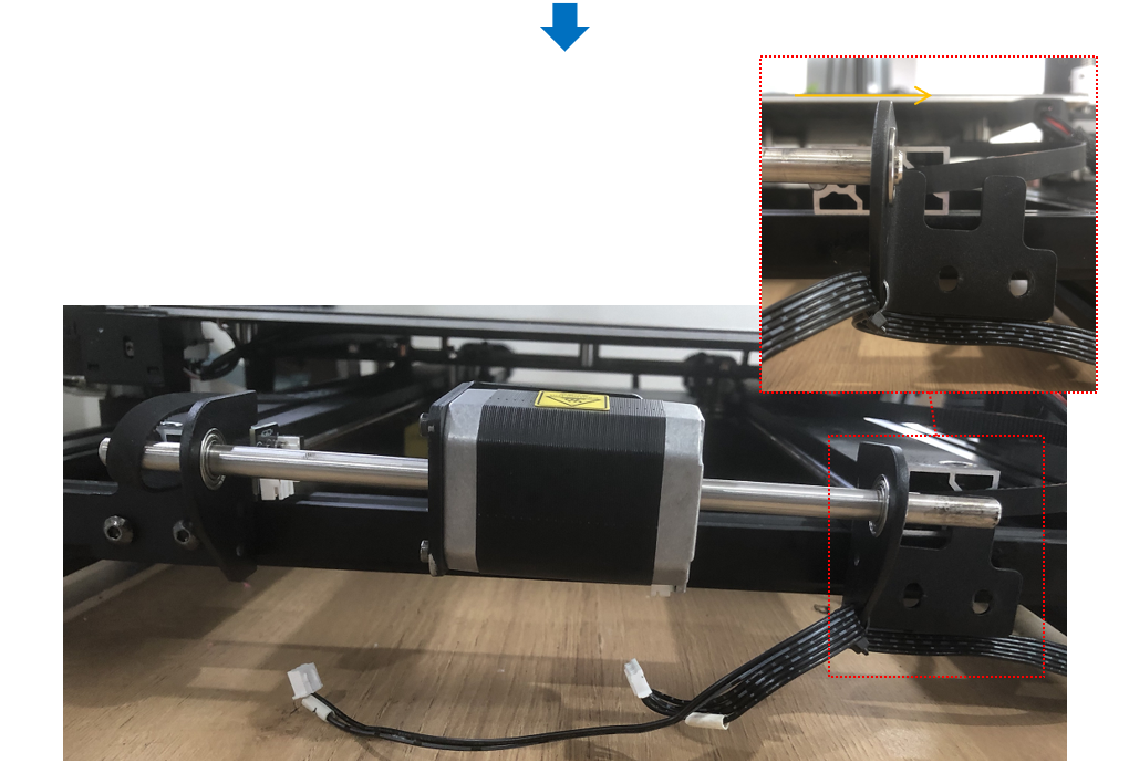
① Use the S3.0 Allen key to loosen the 2 screws fixing the Y-axis motor module for easy removal of the sheet metal.

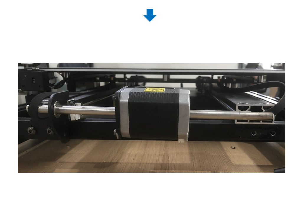
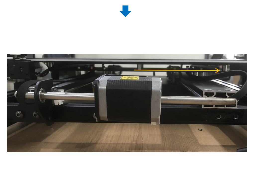
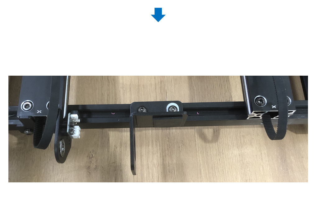
② Remove the belt from the motor shaft on the right, use the S3.0 Allen key to unscrew the 2 screws fixing the right sheet metal, move the sheet metal out from the right side, and the bearing will be removed along with it.
¶ Step 6: Remove the Motor
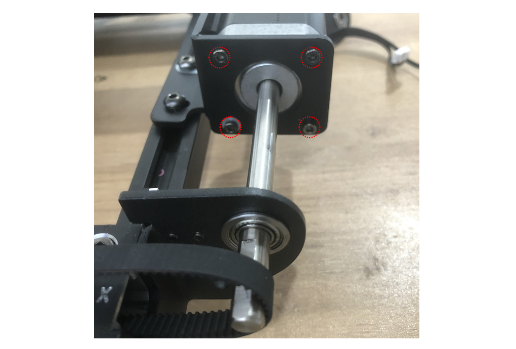
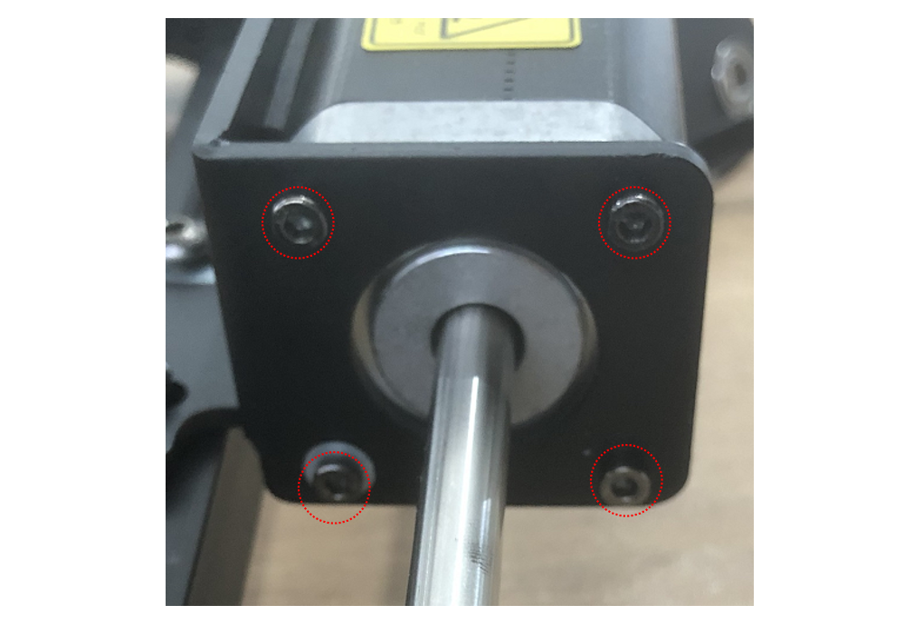
Use the S2.5 Allen key to unscrew the 4 screws fixing the motor, and then move the motor out from the right side.
¶ 3. Test the Motor:
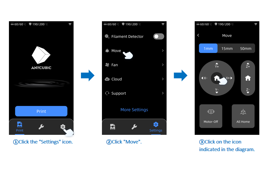
Take out the new Y-axis motor and plug the Y-axis motor cable into the motor connector. Connect the machine to the power source and turn it on. On the main screen, click the "Settings" icon, then "Move" and finally the "Home" icon inside the circle.
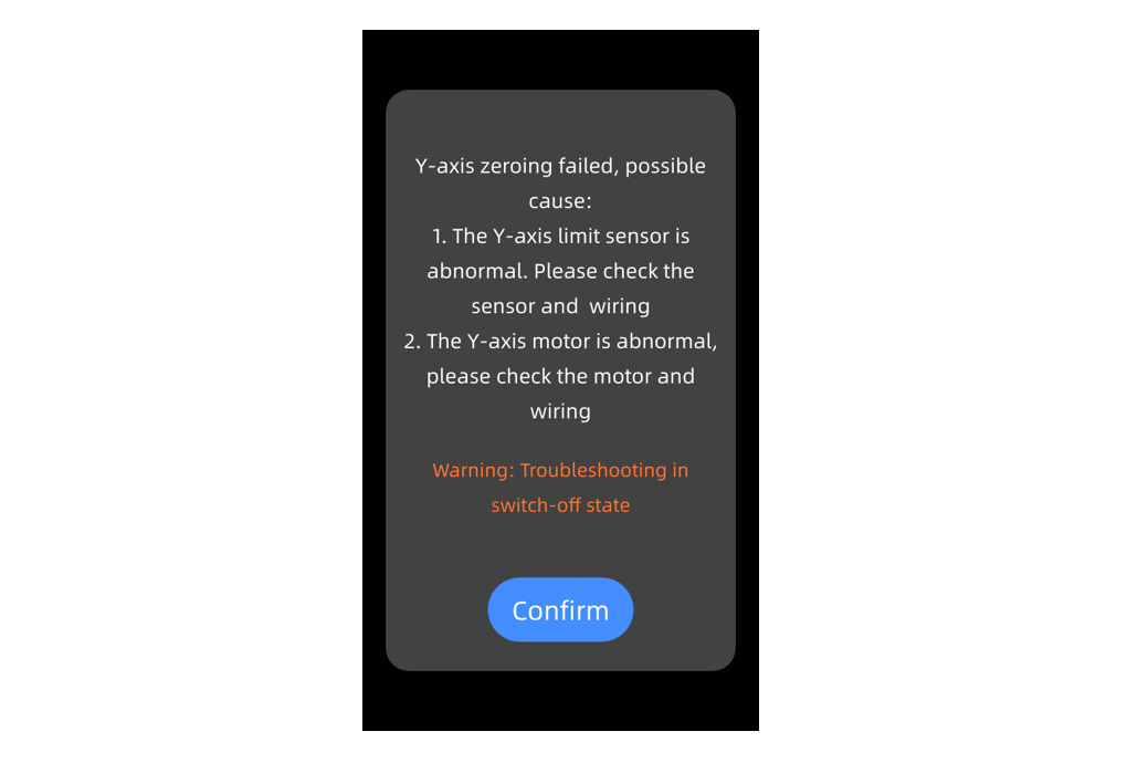
After the X-axis homes, observe whether the new Y-axis motor rotates normally. The machine control screen will display an error message,
"Y-axis zeroing failed, possible cause: 1. The Y-axis limit sensor is abnormal, Please check the sensor or wiring. 2. The Y-axis motor is abnormal, please check the motor or wiring."
This error is normal at this point because we have not yet installed the Y-axis limit switch cable.
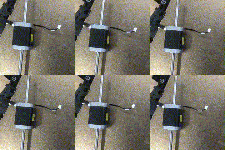
If there is no problem, safely shut down the machine and disconnect the power cord and Y-axis motor cable.
¶ 4. Installation Steps:
¶ Step 1: Install the Motor
Pass the new Y-axis motor shaft through the left sheet metal and align it with the screw holes to install it on the Y-axis fixed sheet metal.
Note:
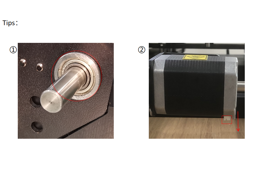
① When passing through the left sheet metal and bearing, press the bearing from the outside to ensure it is flush with the sheet metal.
② The terminal at the motor cable should face downward.
Take out the 4 screws removed earlier and use the S2.5 Allen key to tighten the screws to fix the motor.
¶ Step 2: Install the Right Fixed Sheet Metal
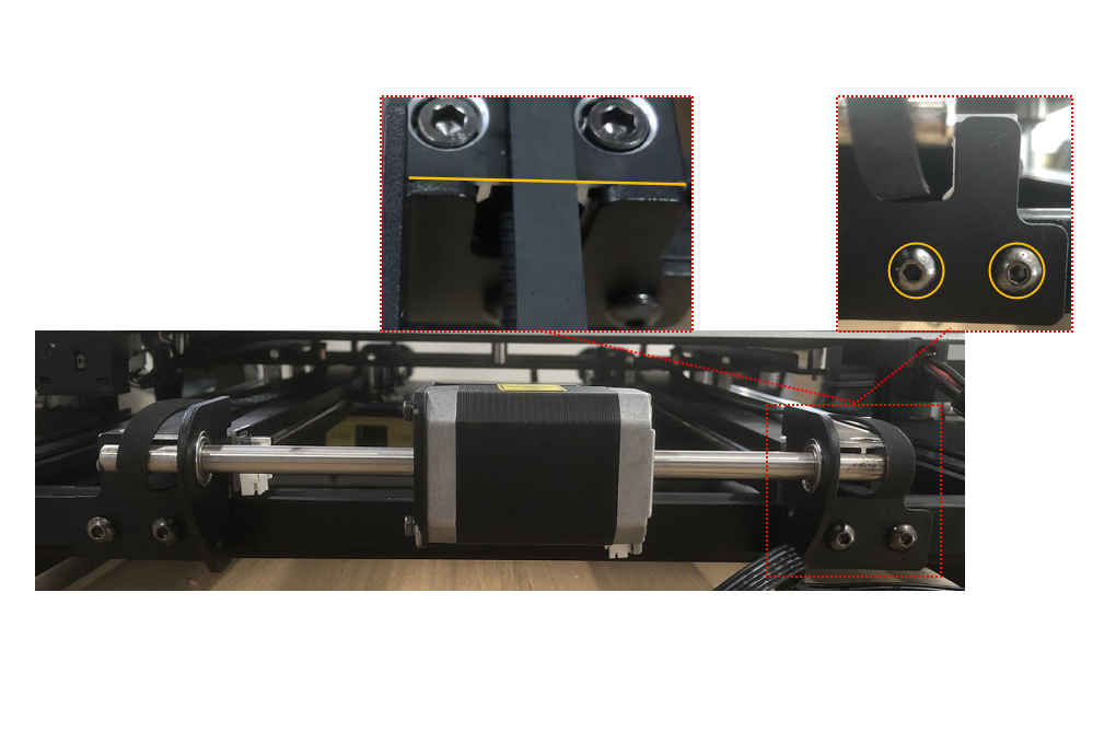
① Take out the right fixed sheet metal and screws removed earlier, pass it through the right Y-axis motor shaft, align it with the screw holes, and use the S3.0 Allen key to pre-lock 2 screws.
Adjust the right fixed sheet metal to be in line with the Y-axis guide rail, tighten the 2 screws.

② Take out the previously removed bearing, pass it through the right fixed sheet metal and move it to the innermost position.
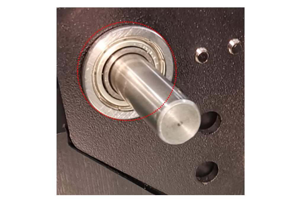
③ Use the S3.0 Allen key to tighten the 2 screws fixing the Y-axis motor module.

¶ Step 3: Install the Synchronous Wheels
① Take out the previously removed synchronous wheels, loosen the set screws on both sides, then install them on the Y-axis motor shaft, bypassing the belts.
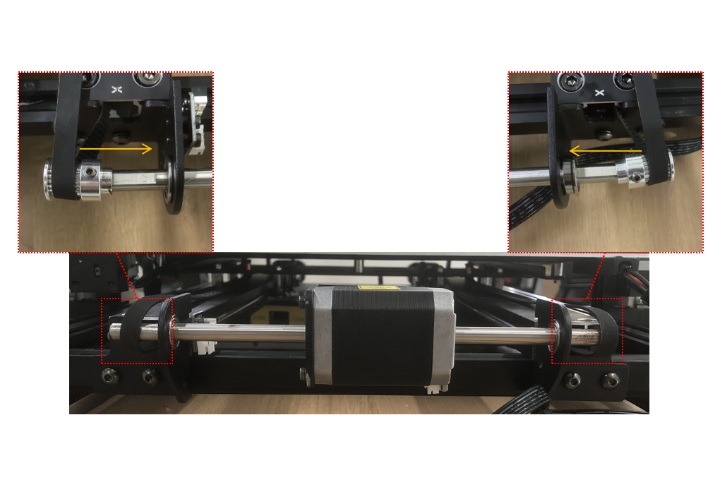
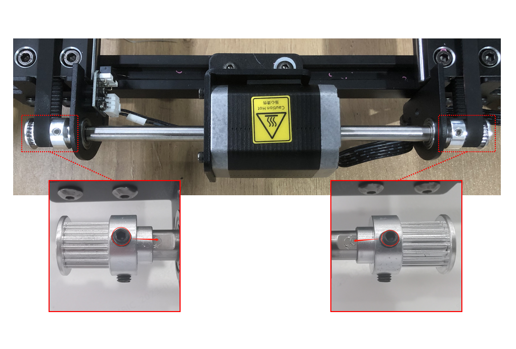
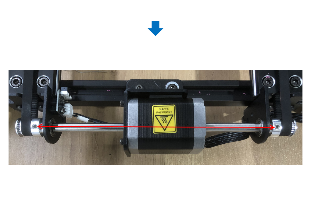
② Adjust the two synchronous wheels, align the set screw on the flat surface of the Y-axis motor shaft, and ensure that the set screws on both sides of the synchronous wheels are on a straight line. Then, use the S2.0 Allen key to tighten the set screw on the flat surface first, and then tighten the other set screw on the other side.
¶ Step 4: Install the Cables
Refer to the diagram, plug in the Y-axis motor cable and the Y-axis limit switch cable.

¶ 5. Adjust the Belt Tension:
Rotate the tensioner knob of the Y-axis clockwise until it is tight, then rotate it counterclockwise once.
After replacement, please re-level your printer.