¶ Tools Required for Inspection:
● M2.5 Allen Key
● Multimeter
¶ 1.Poor Wire Connection
Troubleshooting Steps:
¶ Step 1: Power on the printer
Connect the printer to the power socket using the power cord and turn on the printer.
¶ Step 2: Check for poor heated bed wire connection
Slowly push the heated bed back and forth five times and observe if there is a significant temperature change displayed on the touchscreen during the movement. If there is a large temperature fluctuation, it may indicate a poor connection with the heated bed wire. Try replacing the heated bed to resolve the issue.

¶ Step 3: Power off the printer
Before proceeding with the following steps, make sure to power off the printer and disconnect the power for safety.
¶ Step 4: Disassemble the printer bottom cover
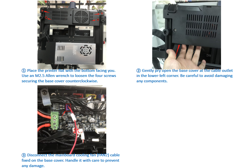
① Place the printer flat with the bottom facing you. Use an M2.5 Allen Key to loosen the four screws securing the base cover counterclockwise.
② Gently pry open the base cover at the cable outlet in the lower-left corner. Be careful to avoid damaging any components.
③ Disconnect the mainboard cooling fan (FAN2) cable fixed on the base cover. Handle it with care to prevent any damage.
¶ Step 5: Reconnect the wires
Try reinserting the heated bed T1 wire connector.
¶ 2.Hardware Troubleshooting
Note: Conducting hardware troubleshooting requires some electrical knowledge, and it is crucial to ensure safety. Follow the steps below for troubleshooting:
Troubleshooting Steps:
¶ Step 1: Power off the printer
Before troubleshooting, ensure the printer is powered off and disconnected from the power source for safety.
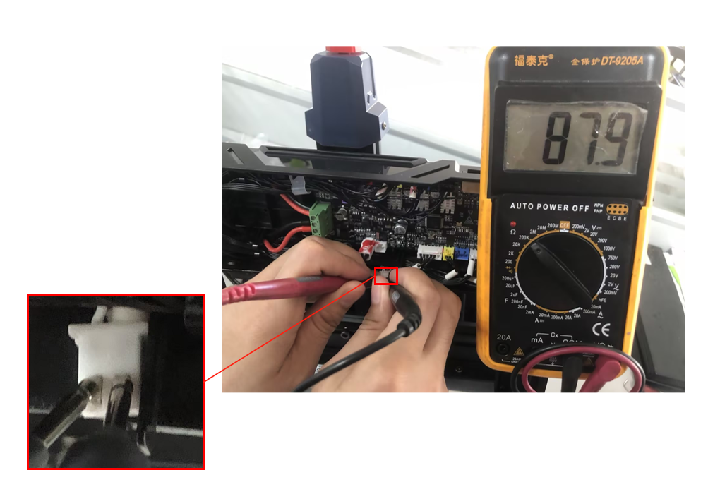
¶ Step 2: Measure the heated bed NTC resistance
Take out the T1 NTC terminal using your hand or a tool. Set the multimeter to the 200KΩ range. With the heated bed at room temperature (25℃), measure whether the resistance of the heated bed T1 terminal falls within the range of 100±15KΩ. If it is not within the range, it may indicate an issue with the heated bed. You could try replacing the heated bed to eliminate the problem.
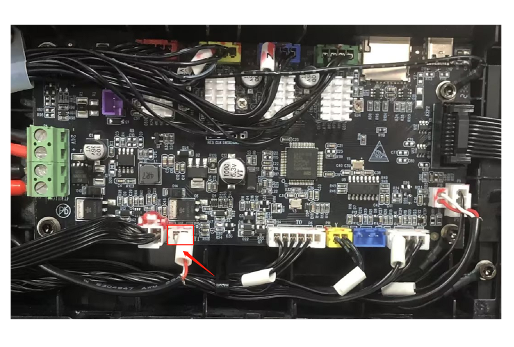
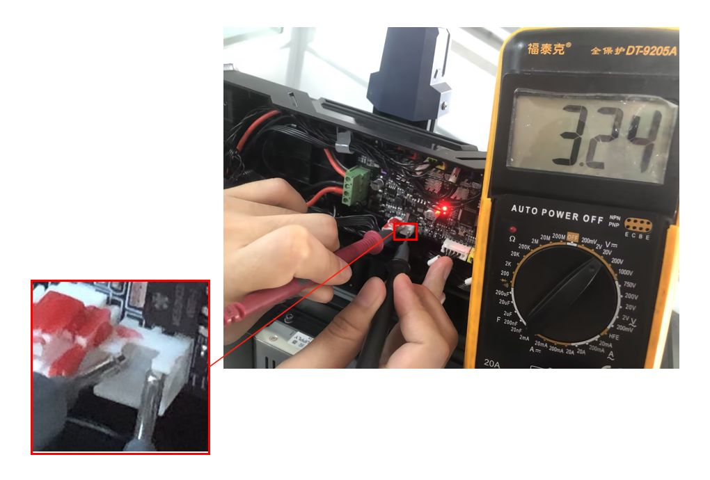
¶ Step 3: Measure the NTC voltage on the mainboard
Connect the printer to the power source and turn it on. Set the multimeter to the 20V DC range. Place the black probe (negative) on the second PIN pin from the left of the mainboard T1 port and the red probe (positive) on the first PIN pin from the left. Measure whether there is a 3.3±0.3V voltage on the NTC PIN pins of the mainboard. If the measured voltage is within the normal range, it indicates that the mainboard is functioning properly. Otherwise, if the measured voltage is not within the range, it may suggest an abnormality in the mainboard. You could try replacing the mainboard. (Note: This method involves working with electricity, please exercise electrical safety and measure as shown in the corresponding position in the diagram.)
For the steps corresponding to the disassembly of components mentioned above, simply follow the opposite sequence when assembling.
If the previous troubleshooting methods were unsuccessful in resolving the issue. We recommend that you create an after-sales work order to provide the after-sales engineer with feedback on the previous inspection process and results. The after-sales engineers will assist you in finding a solution to the problem.(Reply time :1 working day)
Please click this link to submit your ticket: