¶ 1. Tools:
S3.0 Allen key
S2.0 Allen key
¶ 2. Disassembly Steps:
Note: Some illustrations, specifically the bottom heated bed components, have been omitted for better visibility.
¶ Step 1: Power Off the Device
Before replacing the Z-axis timing belt, power off the device and disconnect the power to ensure safe operations.
¶ Step 2: Remove the Z-Axis Top Bearing Fixing Plate
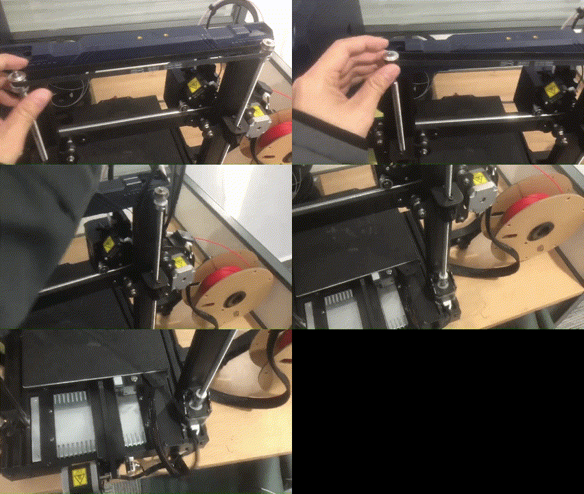
Use the S3.0 Allen key to loosen the two screws on both sides of the Z-axis top-bearing fixing plate.
Take out the fixing plate and screws, placing them aside for later installation.
¶ Step 3: Disassemble the Timing Pulley and Timing Belt
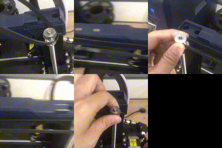
After removing the screw from one side of the timing pulley, take out the pulley and then remove the timing belt.
① Remove the bearing from the timing pulley and place it aside for later installation.
② Use the S2.0 Allen key to remove the two set screws on either side of the Z-axis lead screw, then take off the timing pulley and timing belt.
|
|
 |
¶ 3. Installation Steps:
¶ Step 1: Install Timing Belt and Timing Pulley
① Take the new Z-axis timing belt and the previously removed timing pulley.
Loop the belt around the opposite side's unremoved timing pulley, then loop it around the previously removed timing pulley.
Finally, install the timing pulley onto the Z-axis lead screw.
Note: When installing the timing pulley, the stepped side of the pulley should face upward.
 |
|
② Retrieve the previously removed bearing and install it above the timing pulley.
Note: When installing the bearing, the side with the larger circle should face downward.
¶ Step 2: Install Z-Axis Top Bearing Fixing Plate
Retrieve the previously removed Z-axis top bearing fixing plate and screws.
Place the fixing plate into the installation slots at both ends of the top plastic part (ensure that the side with letters is installed underneath).
Simultaneously fit the fixing plate onto the bearing.
Use the S3.0 Allen key to pre-lock the screws into position, then adjust the position of the bearing fixing plate before tightening the screws.
|
|
|
|
|
¶ Step 3: Tighten Timing Pulley
Push the timing pulley upward and use the S2.0 Allen key to tighten the two set screws on the timing pulley.
¶ 4. Calibration Steps:
After replacing the Z-axis timing belt, it is recommended to recalibrate the device according to the following instructions.
¶ Step 1: Turn On the Device
Connect the device's power cord, press the power switch on the side of the device to start it.
Note:
When inserting the power cord, please avoid crossing it with the print head cable to prevent interference.
¶ Step 2: Calibrate the nozzle position
In the main interface, click on the "Tools" icon - "Control" icon - "Module Calibration" - "Position Calibration."
The machine will automatically perform detection and pause near the top the calibration module.
You could adjust the nozzle to the center position of the calibration module using the distance units and X/Y axis movement direction on the interface.
Once done, click "Save," and finally, perform the automatic leveling again.
¶ Step 3: Automatic Leveling Calibration
On the device's main interface, click the "Tools" icon - "Control" icon - "Auto- Level" - "Confirm" to start the leveling process.
Follow the set process, and after leveling is complete, click "Finish." This process takes approximately 15 minutes.
Note:
① Please check whether the PEI board is installed before leveling.
② The leveling sensor is only used for platforms with metal surfaces.
If you replace the printing platform by yourself, please choose a platform with a metal surface to ensure the normal use of the automatic leveling function.
¶ Step 4: Vibration Compensation Calibration
On the device's main interface, click the "Tools" icon - "Control" icon - "Vibration Compensation" - "Confirm" for resonance detection.
Follow the sequence to detect the X and Y axes. Click "Finish" after the Y-axis detection. This process takes approximately 15 minutes.
Note:
① Place the printer in a spacious and stable area during vibration compensation to avoid interference from other resonance sources.
② There may be significant noise during the vibration compensation process, which is normal.
If the above steps do not provide assistance or if you encounter any other issues during subsequent use, we recommend that you create a support ticket.
The after-sales engineers will assist you in finding a solution to the problem(Reply time :1 working day)
Please click this link to submit your ticket: