¶ 1. Tools:
- S1.5 Allen key
- S2.0 Allen key
- S2.5 Allen key
¶ 2. Disassembly steps:
¶ Step 1: Turn off the printer
Before disassembly, please turn off the printer and disconnect the power supply to ensure safe operation.
¶ Step 2: Remove the print head module
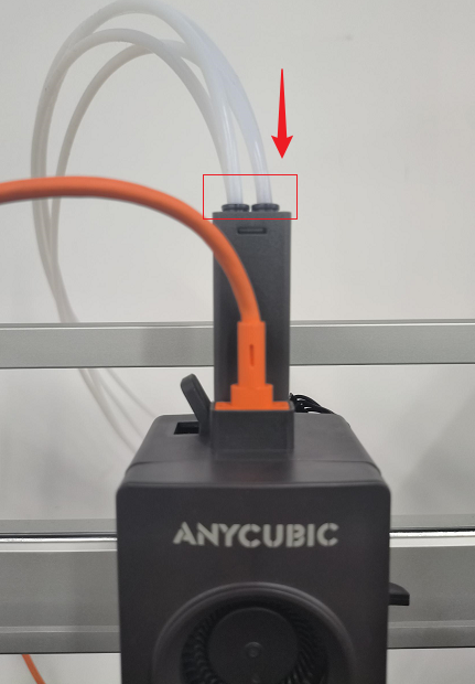
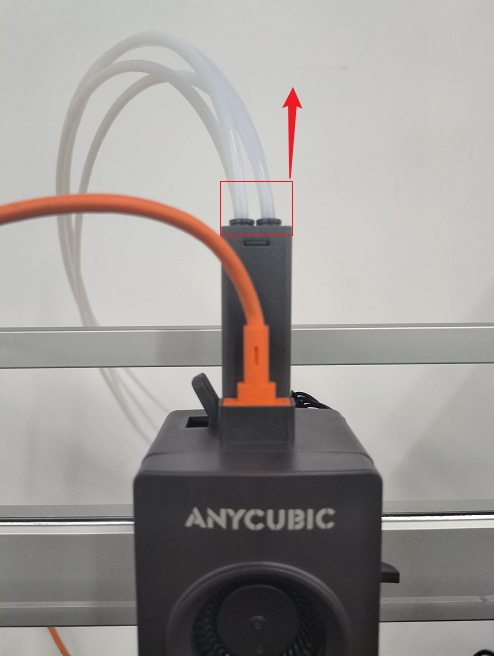
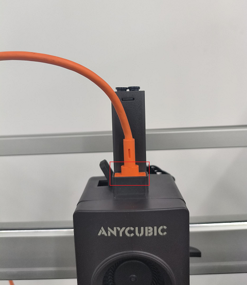
(1) Return the filaments inside the print head to ACE Pro, and then remove the four teflon tubes.
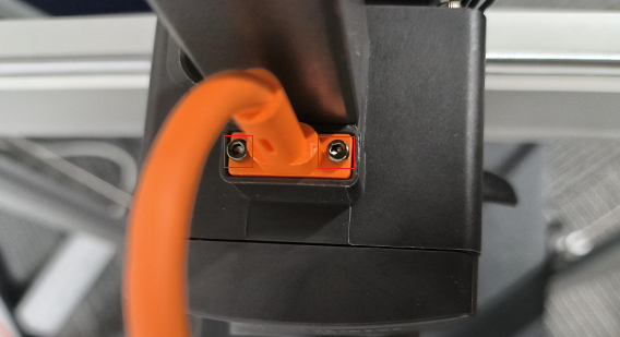
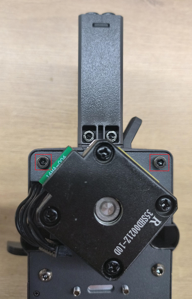
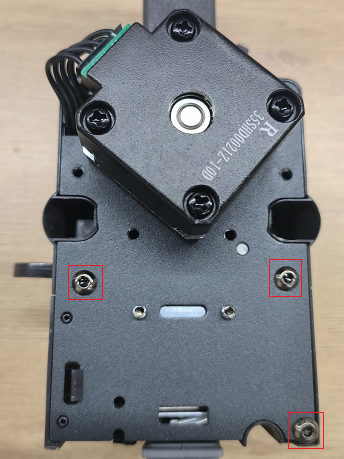
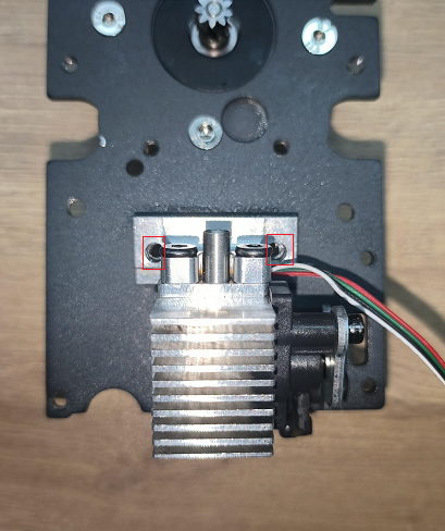
(2) Use the S1.5 Allen key to unscrew the two screws holding the print head cable, and then remove the print head cable.
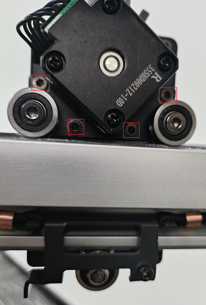
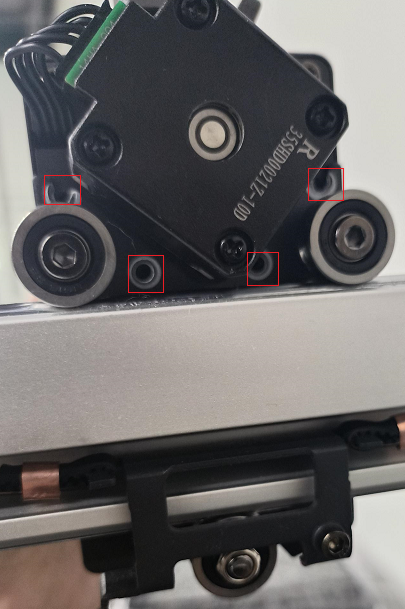
(3) Use the S2.5 Allen key to unscrew the four screws holding the print head module and remove them from the support.
¶ Step 3: Remove the print head front cover
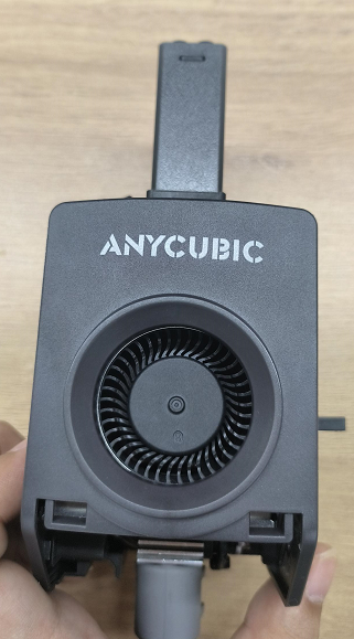
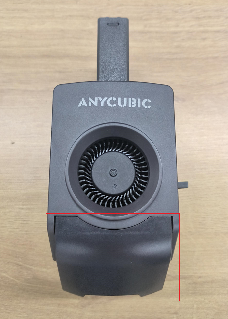
(1) Remove the print head air nozzle assembly, then use the S2.5 Allen key to unscrew the two screws on the back of the print head module.
(2) Press both sides of the print head front cover, and then remove the print head front cover.
¶ Step 4: Remove the model cooling fan
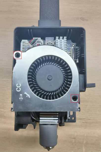
(1) Use the S1.5 Allen key to unscrew the two screws fixing the model cooling fan.
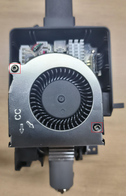
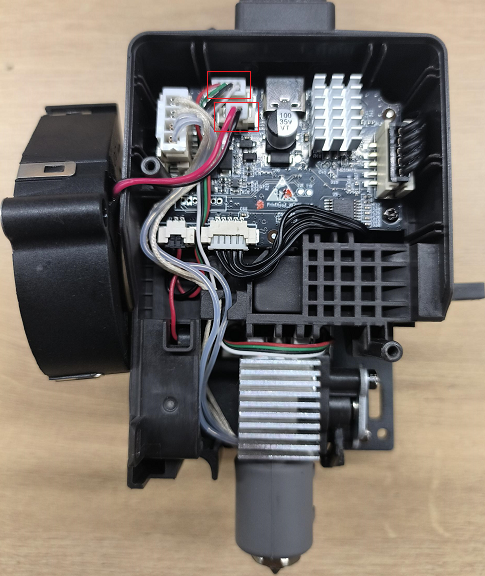
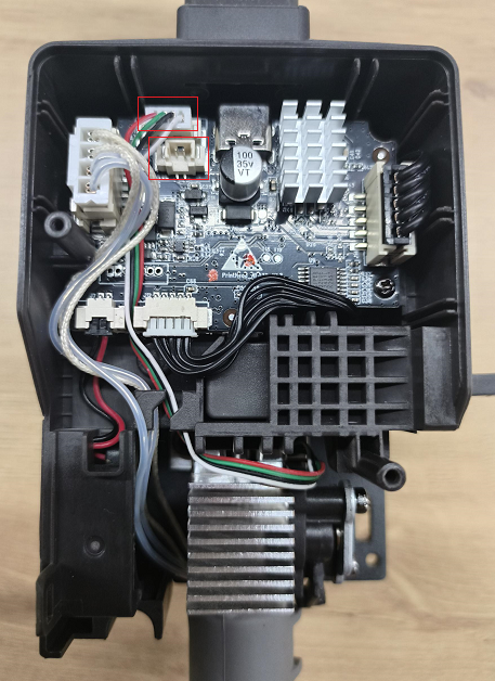
(2) Then remove the strain gauge connection and the cooling fan connection, and remove the model cooling fan.
¶ Step 5: Remove the strain gauge
(1) Use the S2.0 Allen key to unscrew the three screws fixing the back cover of the print head and remove the back cover of the printer.
(2) Use the S2.5 Allen key to unscrew the two screws on the back cover of the print head.
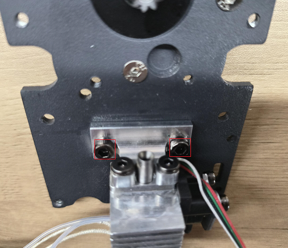
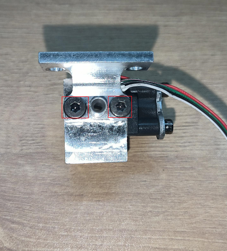
(3) Then use the short handle of S2.0 Allen key to unscrew the two screws fixing the strain gauge.
¶ 3. Installation steps:
¶ Step 1: Install the strain gauge
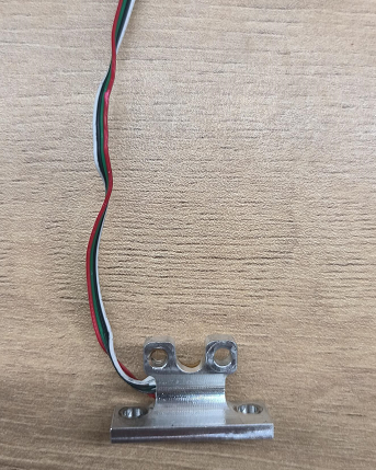
(1) Replace the new strain gauge.
(2) Use a short handle of S2.0 Allen key to tighten the two screws securing the strain gauge, align the strain gauge with the holes on the rear cover, and use an S2.5 Allen key to tighten the two screws on the rear cover.
(3) Then install the back cover of the printer, and use the S2.0 Allen key to tighten the three screws that hold the back cover of the print head.

¶ Step 2: Install the model cooling fan
(1) Replace the new model cooling fan, and then connect the cooling fan connection and strain gauge connection back to the adapter plate.
(2) Use the S1.5 Allen key to tighten the two screws securing the cooling fan.
¶ Step 3: Install print head front cover
(1) Reinstall the print head front cover, then use the S2.5 Allen key to tighten the two screws holding the print head front cover.

(2) Install the air nozzle assembly back into the print head module.
¶ Step 4: Install the print head module
(1) Align the print head module with the holes, and use the S2.5 Allen key to tighten the four screws holding the print head module.
(2) Insert the print head cable back into the print head module, then use the S1.5 Allen key to tighten the two screws holding the print head cable.
(3) Press the black pneumatic joint and install the four teflon tubes back into the four-in-one-out assembly.