Note: This article is written based on the Anycubic Slicer Next slicing software version 1.3.5.3. There may be some differences due to inconsistent software versions.
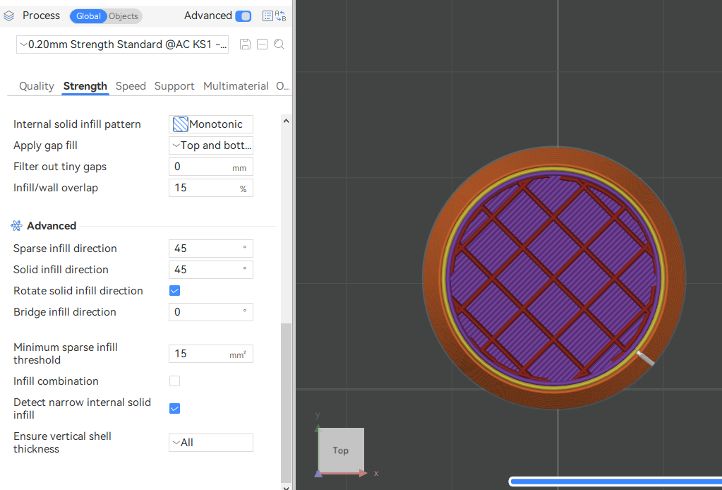
Please open the Anycubic Slicer Next slicing software, and then click "Process" - "Strength" - "Advanced" to set the advanced parameters of the strength.
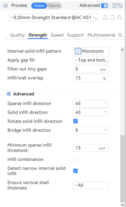
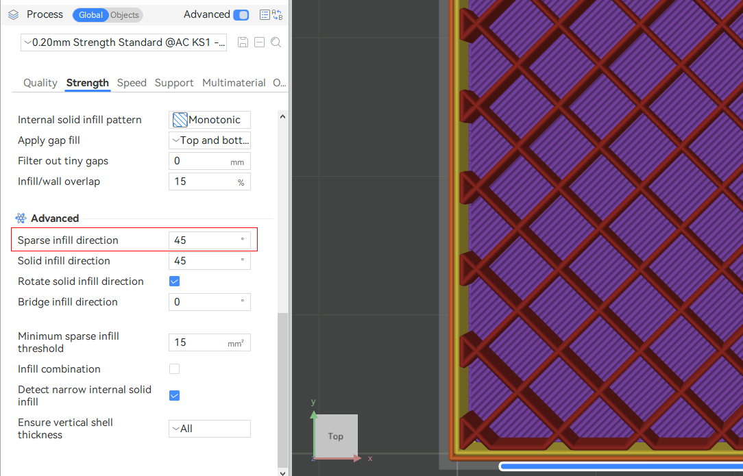
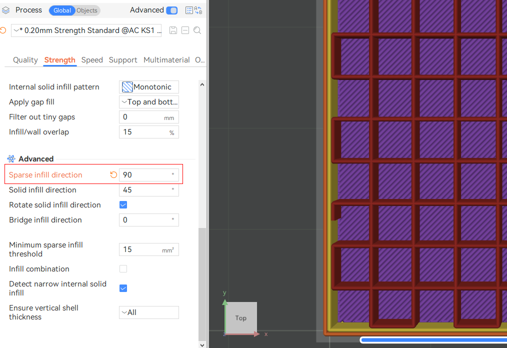
¶ Sparse infill direction:
The Angle of the sparse-filled pattern determines the beginning or overall direction of the routing.
Infill direction 45° :
Infill direction 90° :
¶ Solid infill direction:
Angle of solid infill pattern, which controls the start or main direction of line.
Infill direction 45° :
Infill direction 90° :

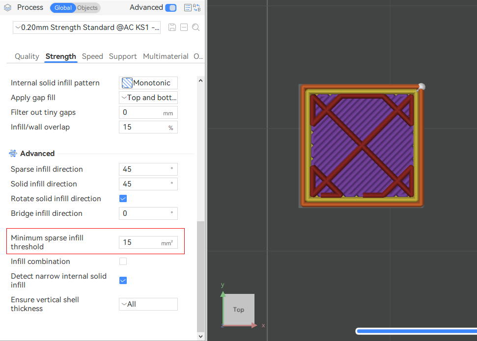
¶ Rotate solid infill direction:
Rotate the solid infill direction by for 90° each layer. If this parameter is cancelled, the model effect is as shown in the following figure.

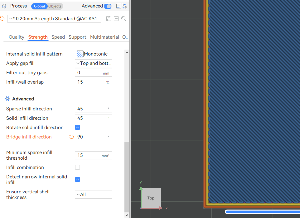
¶ Bridge infill direction:
Bridging angle override. 0 means the bridging angle will be calculated automatically. Otherwise the provided angle will be used for external bridges. Use 180° for zero angle.
Infill direction 90° :
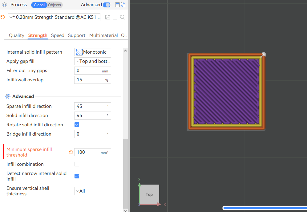
¶ Sparse filling minimum threshold:
Sparse filled areas smaller than this threshold will be replaced by internal solid filling. That is to say, if the area of the internal filling area is less than this set value (default 15mm²), the filling trace type of this area will be internal solid filling; otherwise, sparse filling will be adopted. The main purpose is to improve the strength and fill the small areas with solid fillers.
Take a cube of 1cm³ size as an example:
The minimum threshold for sparse filling is 15mm² :
The minimum threshold for sparse filling is 100mm² :
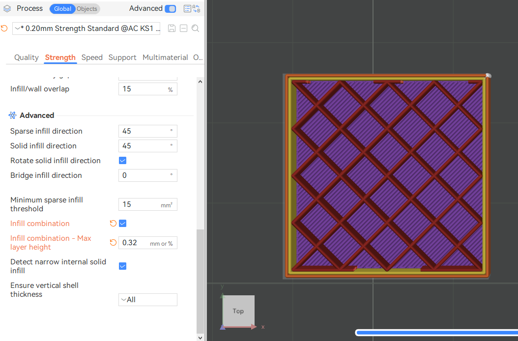
¶ Infill combination:
Automatically merging several layers of sparse fill for printing together can shorten the printing time. The interior and exterior walls still maintain the original floor height printing. You can set the maximum layer height for merging sparse fill to 0 or 100% to use the nozzle diameter, which can minimize the print time to the greatest extent. Or set it to approximately 80% to maximize the sparse fill strength. You can set this value to an absolute millimeter value (for example, to 0.32 millimeters for a 0.4 millimeter nozzle), or a percentage value of 80%.
Note: This value must not be greater than the nozzle diameter.
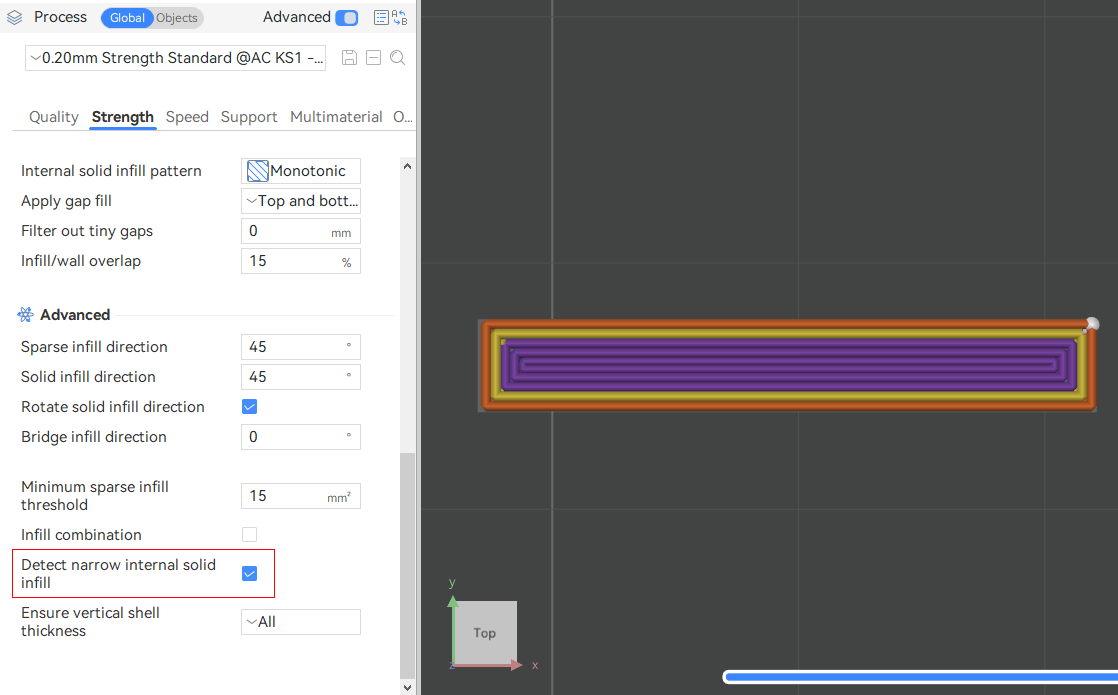
¶ Detect narrow internal solid infill:
This option will auto-detect narrow internal solid infill areas. If enabled, the concentric pattern will be used to speed up the printing process. Otherwise, the rectangular pattern will be used by default.

¶ Ensure vertical shell thickness:
Add solid infill near the sloping surface to ensure the thickness of the vertical shell (top + bottom solid layer). This parameter has four options.
None: Solid fillers will not be added anywhere.
Critical Only: Avoid adding solid fillers to the walls
Moderate: Only add solid filling for severely tilted surfaces
All: Add solid fillers to all appropriately inclined surfaces
Note: If your model has inclined surfaces, please carefully select the "None" option. The default option is "All".