Note: This article is written based on the 1.3.5 version of Anycubic slicer Next slicing software. There may be some discrepancies if the software version is inconsistent.
¶ Introduction to line width
Line width refers to the width of the material line formed by the molten consumables extruded from the nozzle during the 3D printing process. Normally, the line width is basically the same as the diameter of the nozzle, that is, the nozzle diameter determines the approximate width of the extruded material. If you want the line width to be wider or thinner than the nozzle diameter, you can achieve a certain degree of control by adjusting the extrusion flow rate. However, since the nozzle diameter is fixed, if the set line width is too different from the nozzle diameter, it often leads to problems such as uneven extrusion and poor interlayer bonding, thereby affecting the printing quality. Therefore, when printing with nozzles of different calibers, it is recommended to keep the line width setting close to the actual diameter of the nozzle to avoid over-adjustment to ensure a stable printing process and obtain better molding results.
¶ Line Width Settings
In the slicing software, in Process - Quality - Line Width, you can adjust and set the line width of each routing type.
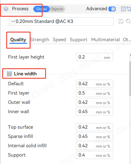
¶ Default
Default line width if other line widths are set to 0. lf expressed as a %, it will be computed over the nozzle diameter
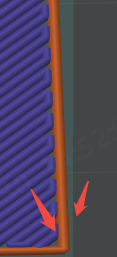
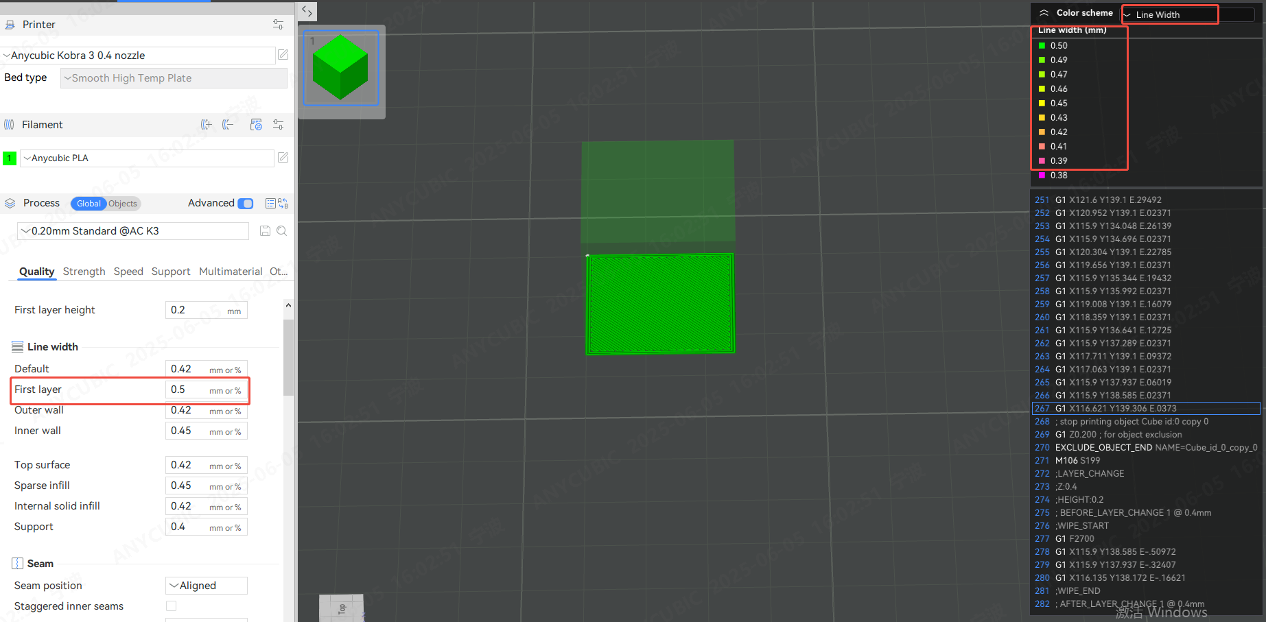
¶ First layer
Line width of initial layer, lf expressed as a %, it will be computed over the nozzle diameter.
When setting the line width for printing the first layer, if there is a conflict with the line width setting of other routing types, the line width of the first layer will still be used. The default line width of the first layer is usually wider, because properly increasing the line width/layer height ratio of the first layer can enhance the adhesion of the first layer and ensure the success rate of printing.
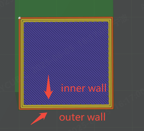
¶ Outer wall/Inner wall
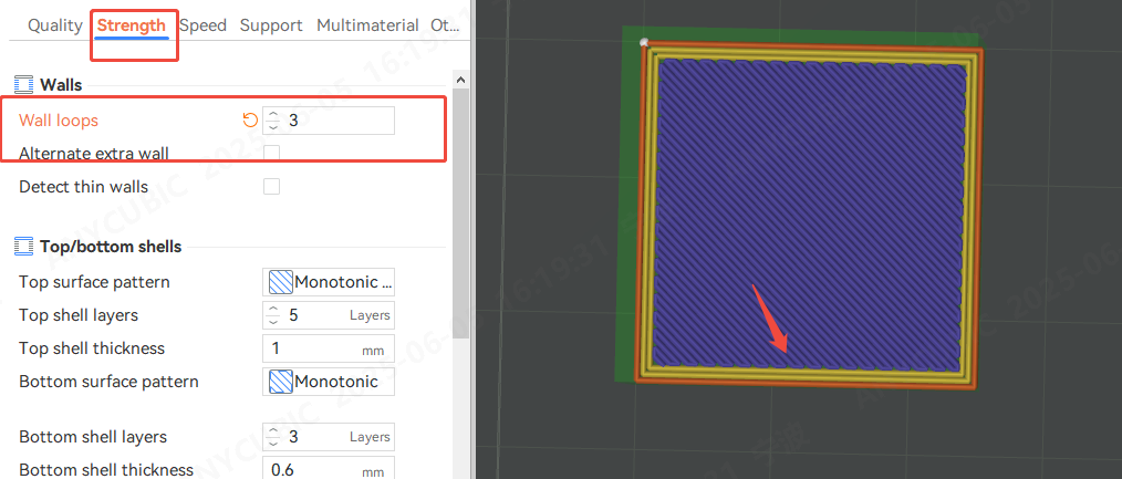
The outermost shell of the model belongs to the Outer wall. The inner side belongs to the Inner wall. No matter how many layers of walls are set for the model, except for the Outer wall, the other layers of walls belong to the Inner wall.
The number of circles of the wall can be changed
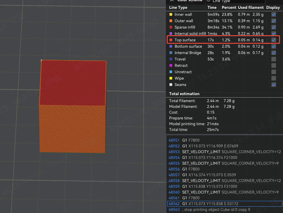
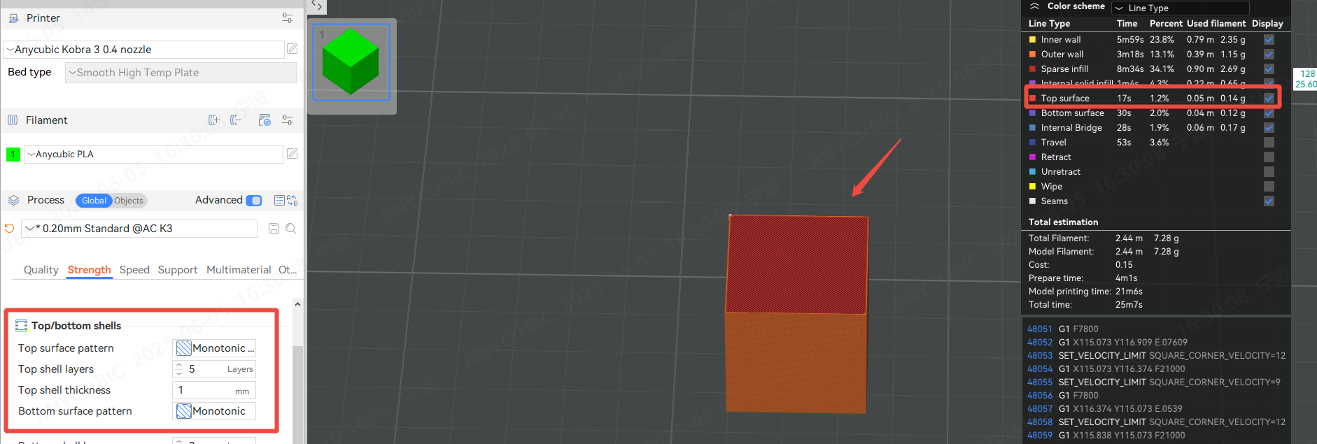
¶ Top layer
Set the line width of the top surface of the model. The top layer refers to the top surface of the model, as shown in the figure below
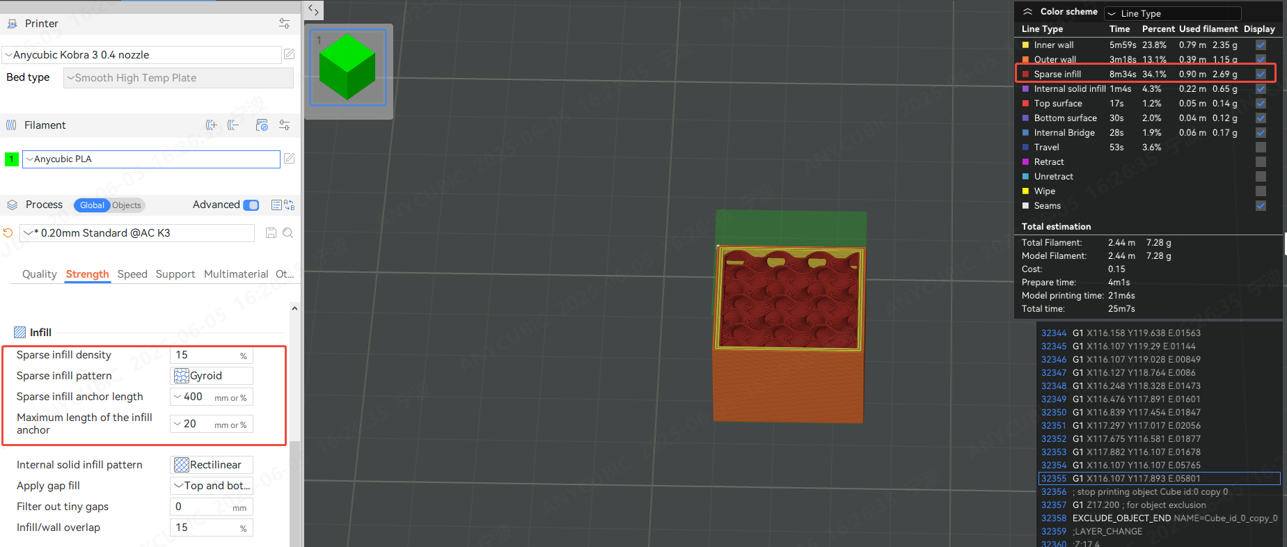
¶ Sparse infill
The line width of the internal sparse filling, except for the top shell and bottom shell layers, any other layers that have a filling area greater than the "minimum sparse filling threshold" are considered sparse filling areas
¶ Internal solid infill
This parameter is used to set the routing line width of the internal solid fill part. When the model has more than one top shell or bottom shell, except for the bottom and top layers, the remaining top and bottom shell layers are considered as internal solid fill layers. In addition, if there are areas inside the model that are smaller than the "minimum sparse fill threshold", these areas will also be identified as solid fills, and their routing lines are also applicable to this setting.
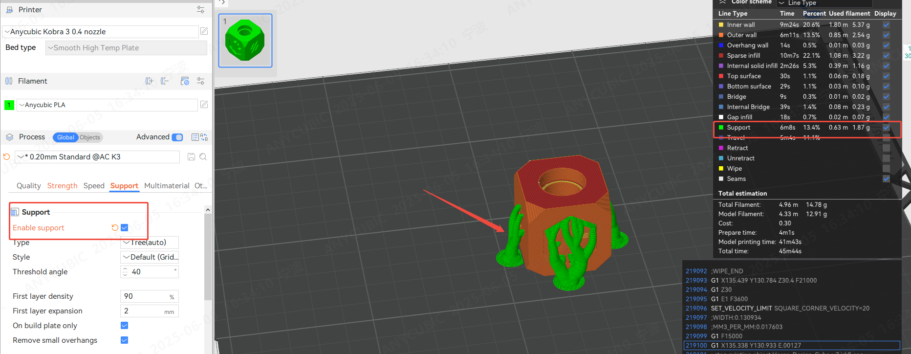
¶ Support
Set the line width of the support and support interface