¶ Walls and surfaces:
Please find Process - Quality - Walls and surfaces in Anycubic Slicer Next and set the advanced parameters of quality.
¶ Walls printing order:
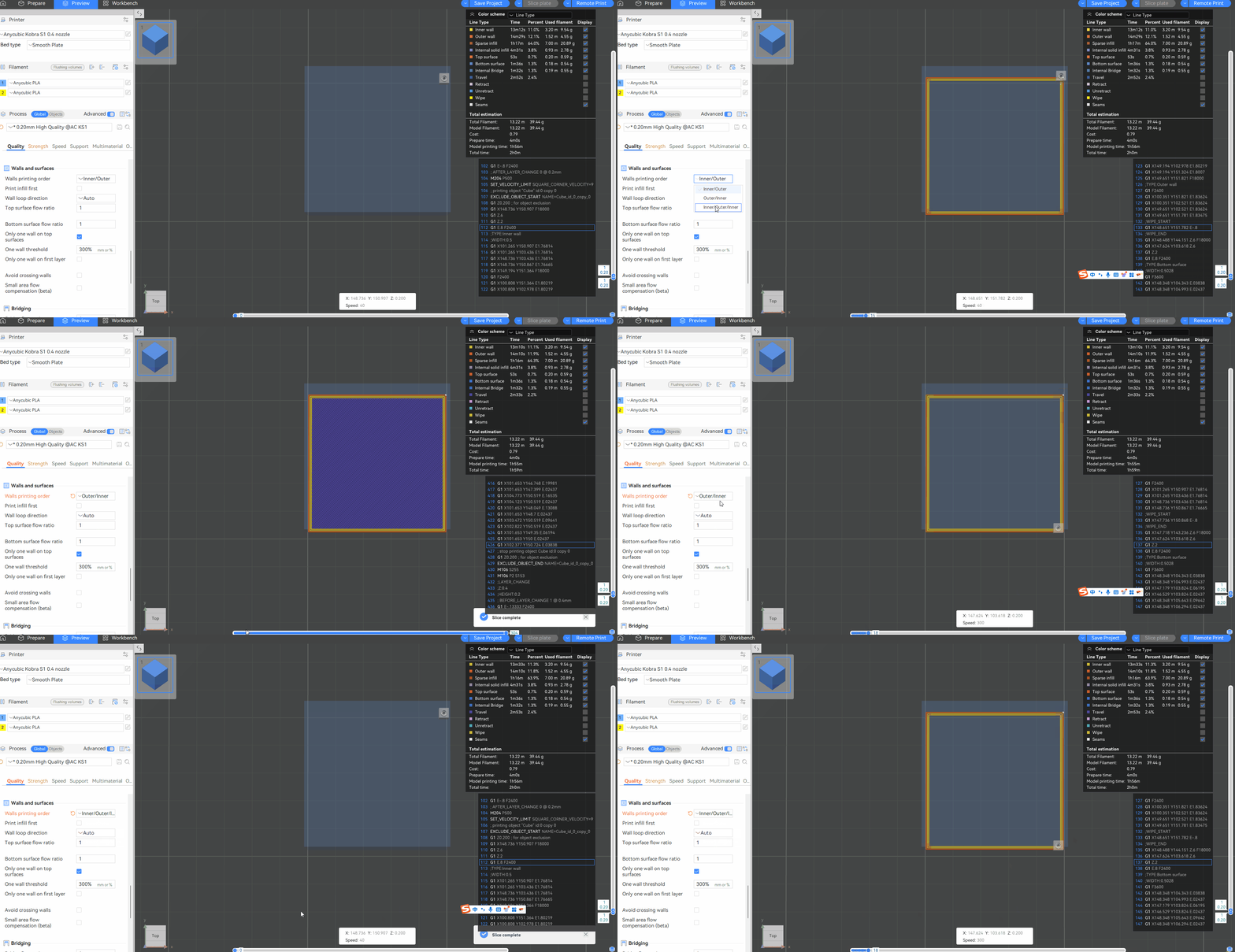
The printing sequence of the inner and outer walls can be adjusted. Currently, there are three options, namely Inner/Outer, Outer/Inner and Inner/Outer/Inner.
Inner/Outer:
Choosing Inner/Outer can achieve the best overhanging effect, as the overhanging walls can adhere to adjacent contours during the printing process. However, it will lead to a slightly reduced surface quality because the exterior wall deforms due to being squeezed into the interior wall.
Outer/Inner:
Choosing Outer/Inner can result in better exterior wall quality and dimensional accuracy, but the Z-joints may look inconsistent because the first extrusion of the new layer begins on the visible surface.
Inner/Outer/Inner:
Choosing Inner/Outer/Inner walls can achieve the best surface finish and dimensional accuracy, as the exterior walls are printed from the inner contour without interference. However, the overhang performance will be reduced because there is no inner contour to support the printing of the exterior wall. Additionally, this option requires at least three walls to take effect, as it starts with the inner wall of the third contour, then the outer wall, and finally the first inner wall.

¶ Print infill first:
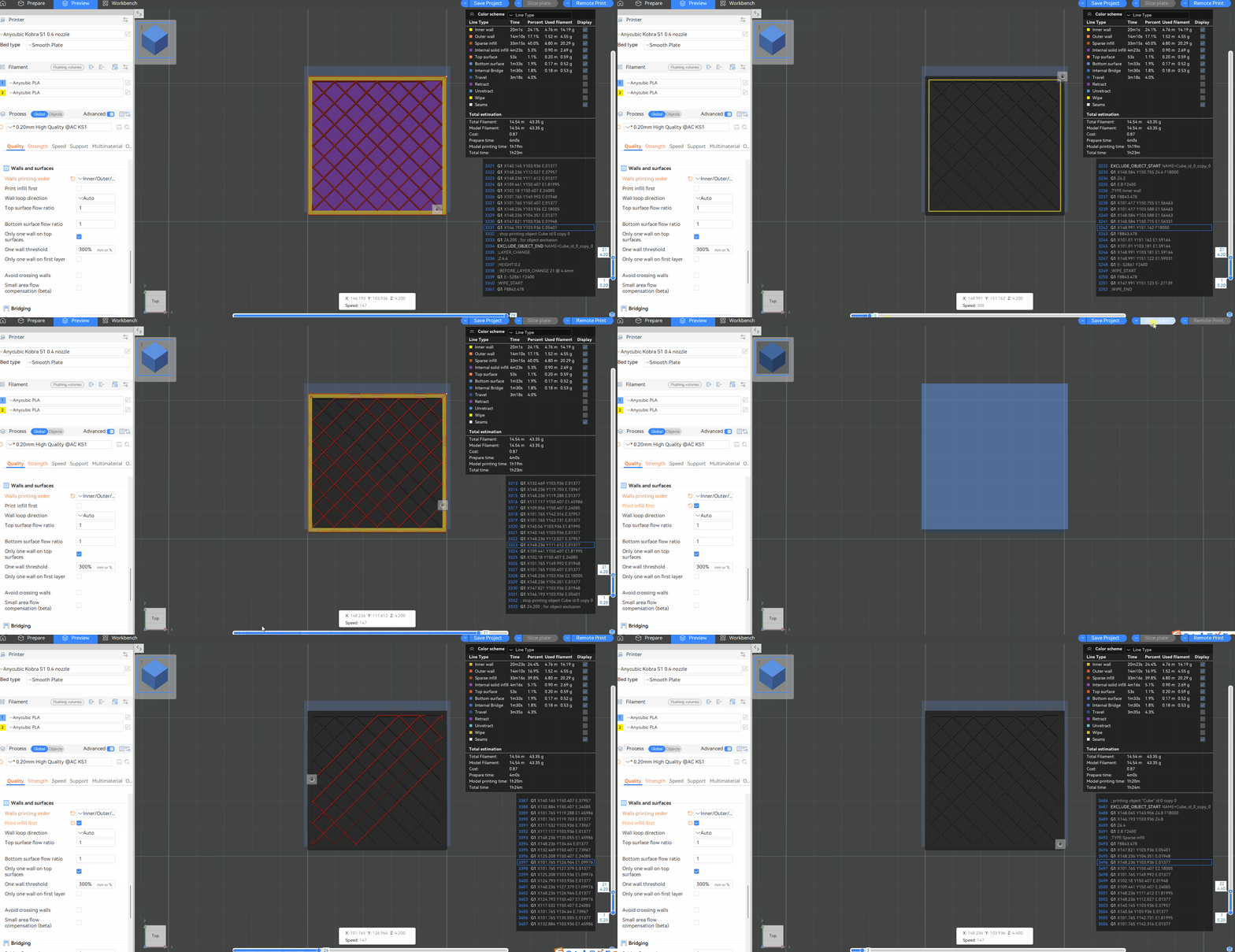
If this function is not checked, the wall will be printed first, which works best in most cases. If this option is checked, the filling part will be printed first, which is helpful for extreme overhanging because the wall has adjacent fillers that can adhere to it. However, the filler will slightly push out the printed wall at the connection, resulting in a poorer surface finish.

¶ Wall loop direction:
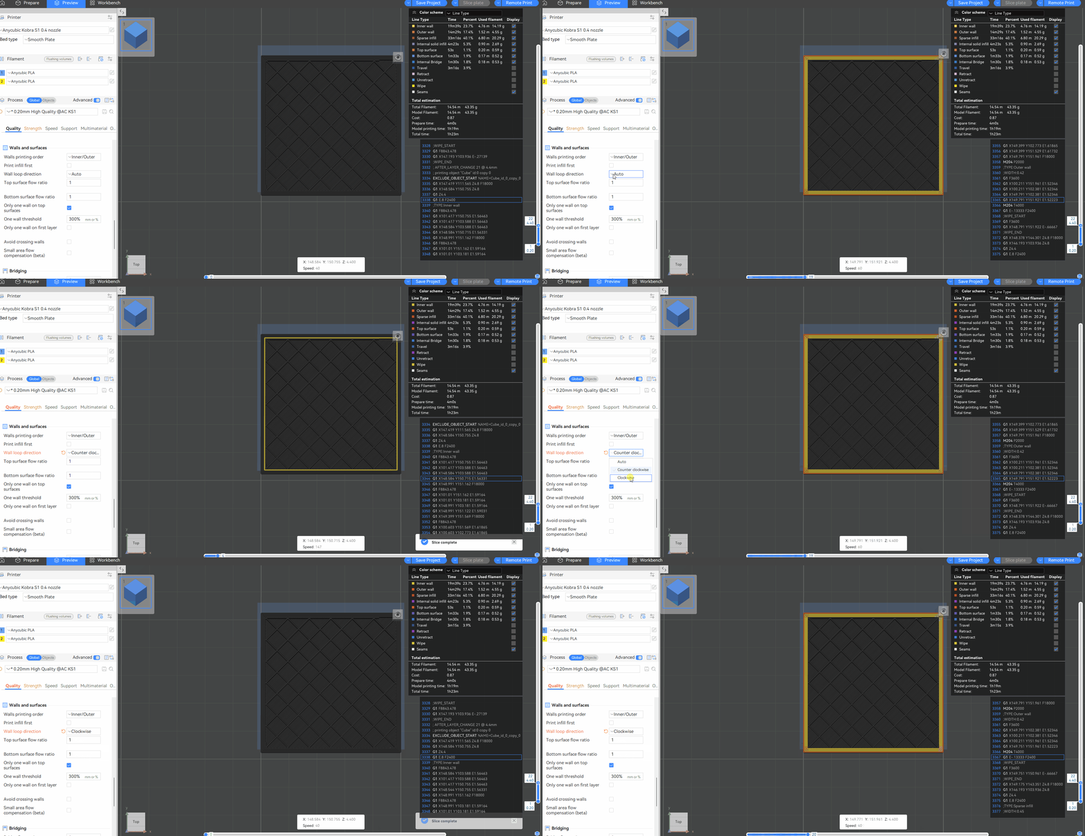
This option indicates the direction in which the wall loop is extruded when looking down from the top. By default, all the walls are extruded counterclockwise. Unless even layer inversion is enabled. If any option other than "Auto" is selected, the direction of the wall will be forced. Additionally, if the spiral vase mode is enabled, this option will be disabled.

¶ Flow ratio:
The consumables may undergo volume changes after switching between the molten state and the crystalline state. This setting proportionally changes all extrusion flows of this consumable in the gcode. The recommended value range is between 0.95 and 1.05. You can adjust this value to achieve a good flat surface in the case of slight overflow or insufficient extrusion.
Flow ratio of top/bottom surface: This parameter affects the amount of material for the solid filling at the top/bottom. You can slightly reduce this value to obtain a smooth model surface. However, the actual top surface flow rate is calculated by multiplying this value by the flow rate ratio of the consumable wire, and if set, by multiplying it by the flow rate ratio of the object.
¶ Only one wall on top surfaces:
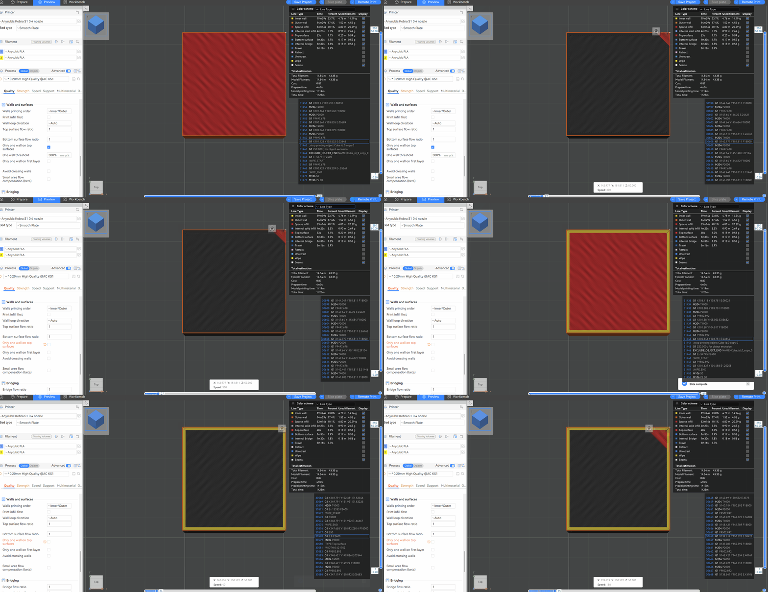
This function is enabled by default, indicating that only a single layer of wall is used on the top surface, thus allowing for more space to use the top filling pattern. If the box is unchecked, the number of walls on the top side will be the same as that on the other sides.
One wall threshold: If the top surface needs to be printed but a part of it is covered by other layers, then when its width is less than this value, it will not be regarded as the top layer. This setting can be used to avoid triggering the "single-layer wall on the top surface" on the narrow top surface.

¶ Only one wall on first layer:
The first floor only uses a single layer of walls, thus allowing more space to be filled with underfill patterns, as shown in the following figure.
¶ Avoid crossing walls:
When driving empty, bypass the exterior walls to avoid spots on the model's surface. Checking this option will result in a better model surface.
Avoid crossing walls - Max detour length: The maximum detour distance when avoiding crossing exterior walls. When the detour distance is greater than this value, this empty run will not detour. The detour distance can be expressed as an absolute value or as a percentage of the empty running length relative to a straight line.
¶ Overhangs:
¶ Detect overhang walls:
Enabling this function can detect the overhang percentage relative to the line width and print at different speeds. For 100% overhang, the bridging speed will be used.
¶ Smooth speed discontinuity area:
Add speed transitions between discontinuous areas. Overhanging and non-overhanging areas usually have significant speed variations. Enabling this option can make the speed transitions smoother to enhance the cooling effect. This option is enabled by default.
¶ Smooth coefficient:
It is used to control the length of the smooth transition path. The smaller this value is, the longer the area of the speed transition will be, which means that the speed transition will be smoother. Appropriate adjustment of the smoothness coefficient can improve the print quality of the overhang area. It is usually recommended to set it within the range of 1 to 200.
¶ Make overhangs printable:
This option can modify the geometry so that the overhanging part of the model does not require support materials or bridge printing.
¶ Reverse on even:
On the even-numbered layers, for the perimeter of those overhanging parts, extrude in the opposite direction. This alternating extrusion pattern can significantly improve steep overhangs. This setting can also help reduce the warpage of the part by reducing the stress within the part wall.