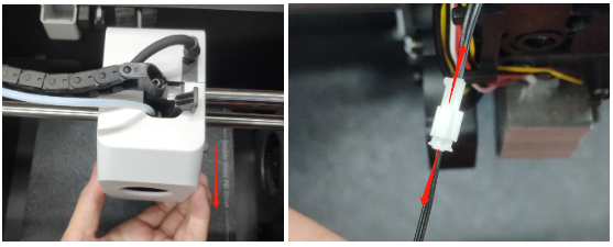
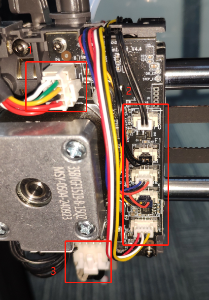
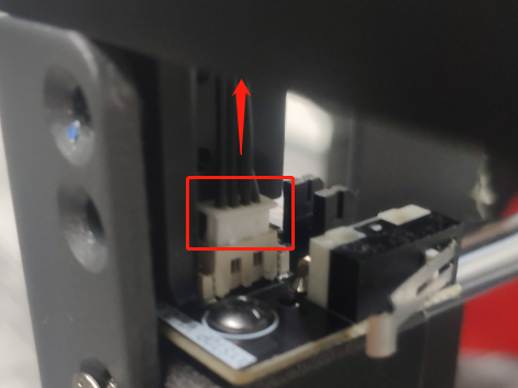
1. Remove the wire harness of the material break detection board, the wire harness plug of the cutter detection board, the wire harness plug of the print head, and the wire harness plug of the hot end of the print head.
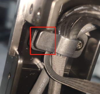
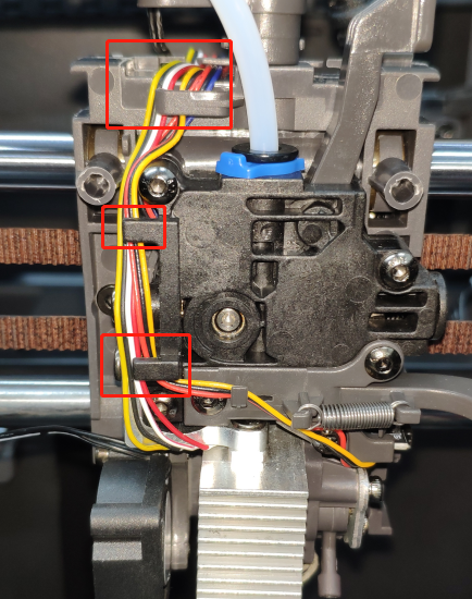
2. Remove the wire harness stuck in the extruder from the buckle.
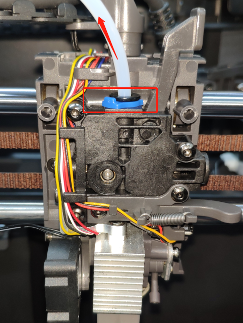
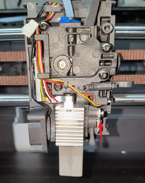
3. Pull the buckle that fixes the quick-release hot end upward, unplug the quick-release hot end connection, and then remove the quick-release hot end.
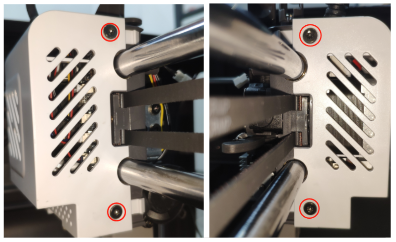
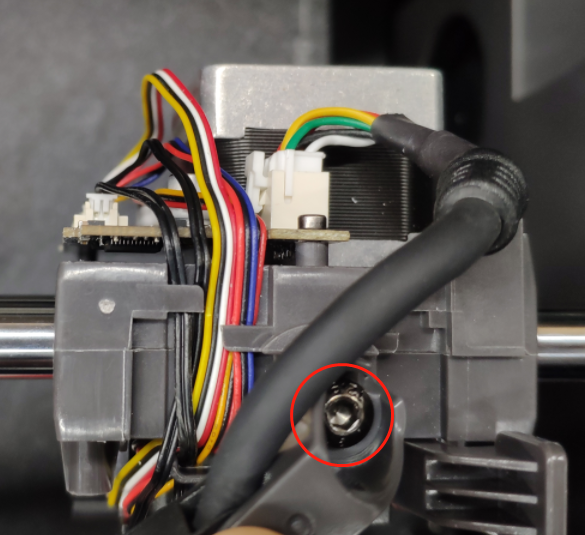
4. Use an S2.5 Allen Key to unscrew the drag chain fixing screws.
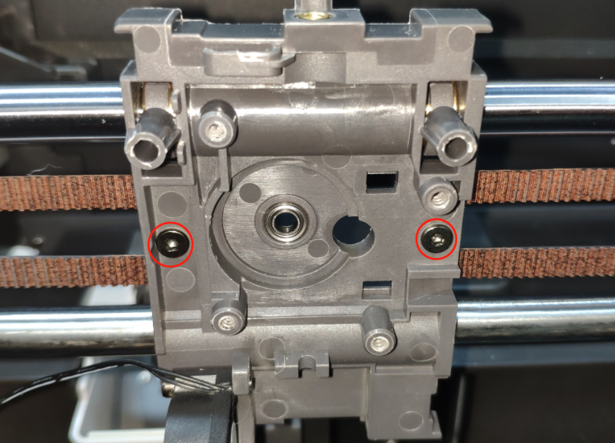
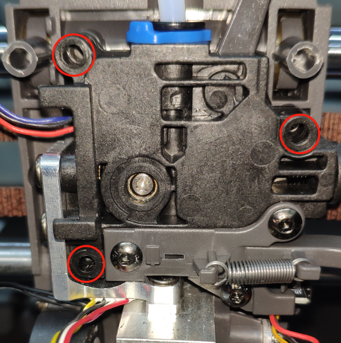
5. Use an S2.0 Allen Key to unscrew the extruder module fixing screws and remove the extruder module.
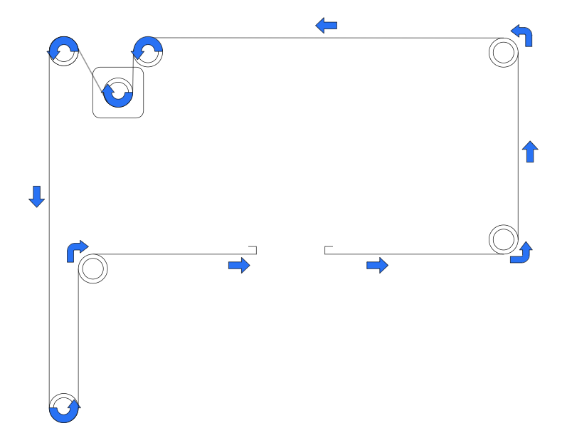
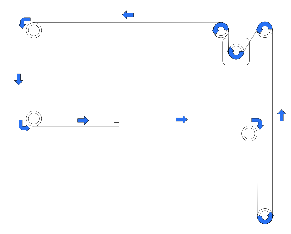
Synchronous belt direction Installation diagram Synchronous belt
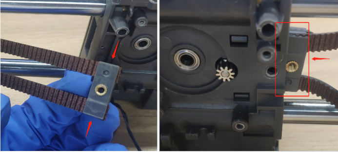
2. Press the belt into the synchronous belt pressure block, put the pressed synchronous belt pressure block into the X axis assembly, and use a 2.0 Allen Key to unscrew the synchronous belt pressure block fixing screws.
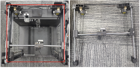
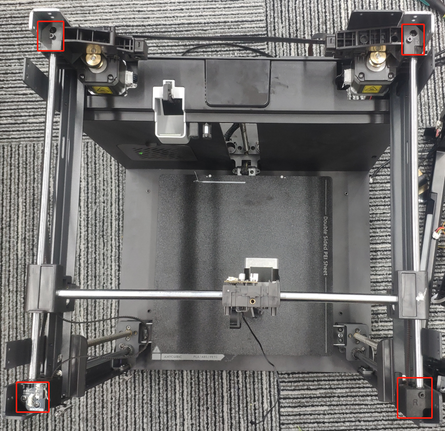
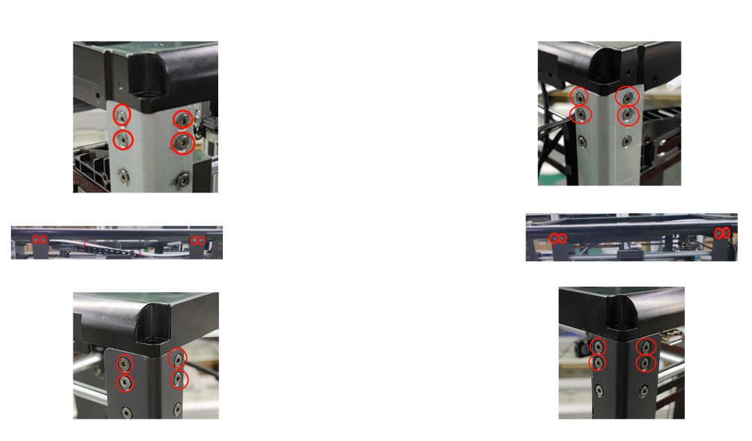
1. After the synchronous belt is inserted, put the four fixing seats of the XY assembly flush into the machine frame, and check whether the synchronous belt is in place.
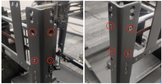
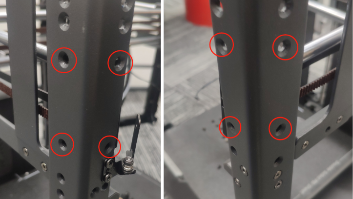
2. Use an S2.0 Allen Key to tighten the countersunk Allen screws of the XY axis assembly.
3. Use an S2.0 Allen Key to tighten the countersunk Allen screws of the XY axis assembly.
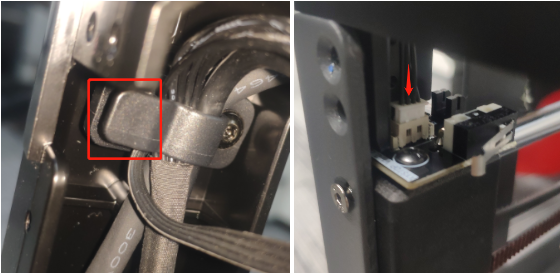
1. Install the XY limit switch wires and clip other harnesses into the hub.
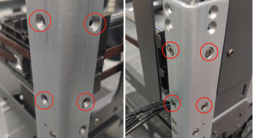
2. Use an S2.0 Allen Key to tighten the countersunk Allen screws that fix the top frame and the two side fixing plates.
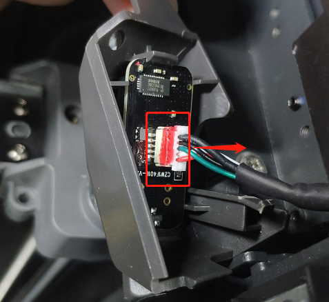
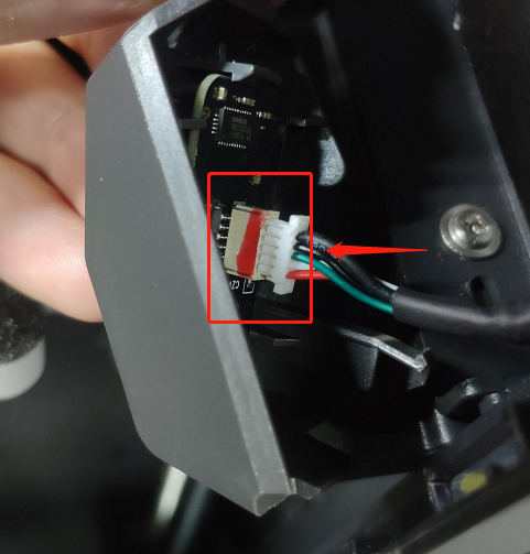
3. Insert the camera harness into the camera module terminal.
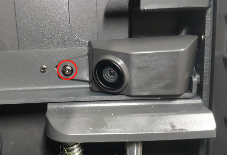
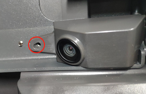
4. Use an S2.0 Allen Key to tighten the screws that fix the camera housing.
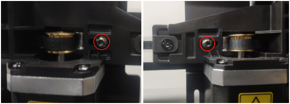
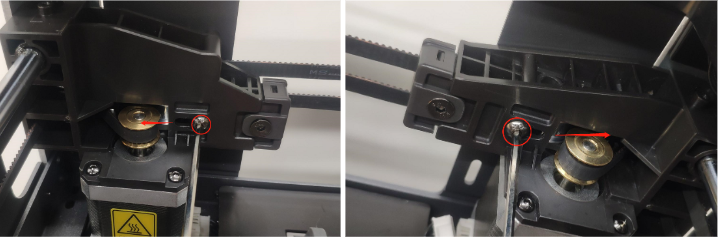
5. Tighten the belt tensioner and pull the tensioner outward.
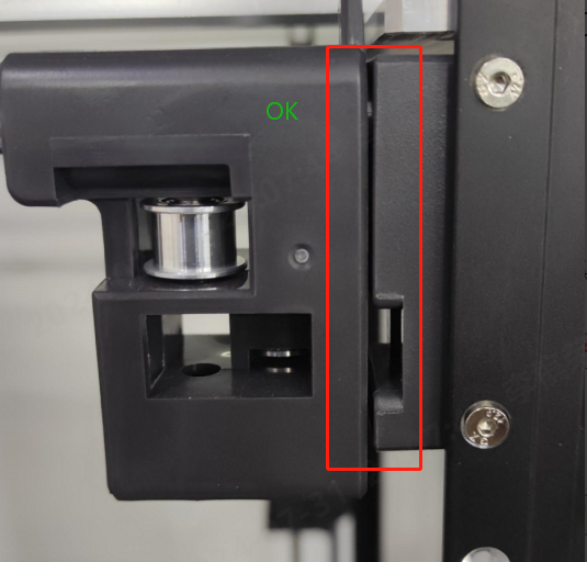
Tip: Slide the X-axis module back and forth twice, move the X-axis to the front of the fixed seat, and check whether the Y-axis slider is close to the fixed seat, as shown in the figure. If it is close to the fixed seat, it is OK, and if there is a large gap between the two, it is NG.
1. Install the extruder module on the X-axis assembly and tighten the extruder module fixing screws with an S2.0 Allen wrench.
2. Insert other harnesses into the slots.
3. Install the material break detection board harness, cutter detection board harness plug, print head harness plug, and print head hot end harness plug.
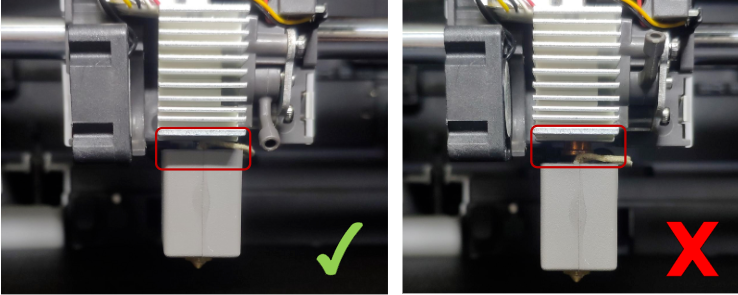
4. Place the quick-release hot end into the heat sink, and pull the buckle down to tighten the hot end.
Check whether the print head is in place.
5. Use an S2.5 Allen Key to unscrew the drag chain fixing screws.