¶ 1. Differences in Support Structure Shapes
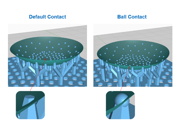
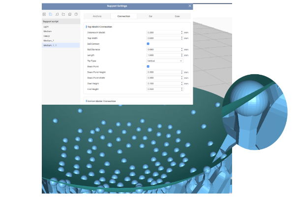
Taking Anycubic Photon Workshop 3.0 as an example, the shape of the support contact points can be categorized as "Default Contact" and "Ball Contact".
Not selecting "Ball Contact" means "Default Contact".

The most significant difference between the two types of support structures is that different processing methods are required to obtain a "perfect" model after removing the supports.
Default contact: After removing the supports, the model surface will have indentations, which need to be treated with "hole filling" to obtain a smooth surface.
Ball contact: After removing the supports, the model surface will have protrusions. The protrusions can be easily eliminated by sanding, which is simpler than "hole filling".
The following diagram shows the cross-sectional views of the two types of support structures:
¶ 1)Default Contact
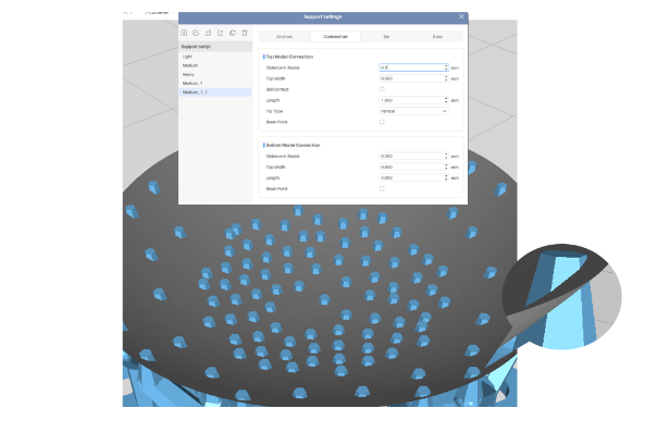
The model surface will have indentations after removing the supports. The larger the "Top Width" and "Distance In Model" values, the larger the indentations will be when removing the supports.
¶ 2)Ball Contact
If only ball contact points are embedded into the model, the model surface will have protrusions after removing the supports. However, in most cases, a small number of non-ball contact support points are also embedded, leading to a large number of protrusions and a few indentations on the model surface.
To eliminate the indentations, the "Top Width" can be reduced or the "Ball Diameter" can be increased.
The contact points can be checked by dragging the layer progress bar after slicing. If there are some supporting columns in addition to the ball contact points, there will be indentations after removing the supports. In this case, the "Top Width" can be reduced or the "Ball Diameter" can be increased.
Note:
Reducing the "Top Width" may cause the supports to not hold onto the model, leading to the model falling into the resin tank after printing. Increasing the "Ball Diameter" will increase the range and height of the protrusions on the model surface.
¶ 2. Setting the "Break Point" of Supports
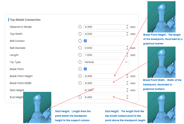
Anycubic Photon Workshop 3.0 slicing software has added a "Break Point" function for supports. Its purpose is to set breakpoints on the contact points where the supports are inserted into the model surface, which facilitates the post-processing of the model.
¶ 3. Examples of setting the Light, Medium, and Heavy supports
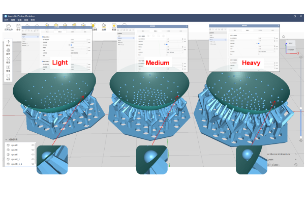
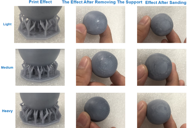
The most obvious difference between the three types of supports - Light, Medium, and Heavy - is that the heavier the support, the better it can support the model and improve the printing success rate. However, heavier supports often mean larger holes or bumps left behind after the supports are removed, resulting in a poorer surface finish and more difficult post-processing.
¶ 1) Default contact shape
Support removal convenience: Light > Medium > Heavy
Support polishing difficulty: Heavy > Medium > Light
Model surface finish after polishing: Light > Medium > Heavy
Printing success rate: Heavy > Medium > Light


¶ 2) Spherical contact shape
Support removal convenience: Light > Medium > Heavy
Support polishing difficulty: Light > Medium > Heavy
Model surface finish after polishing: Light > Medium > Heavy
Printing success rate: Heavy > Medium > Light
¶ 4. Examples of support Break Point settings
We will use a sphere as a model and set the corresponding support contact points for printing tests, observing the printing effect, the effect after removing the supports, and the effect after sanding.
¶ 1) Default contact, no break point
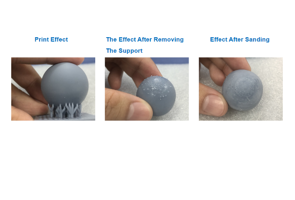
¶ 2) Ball contact, no break point
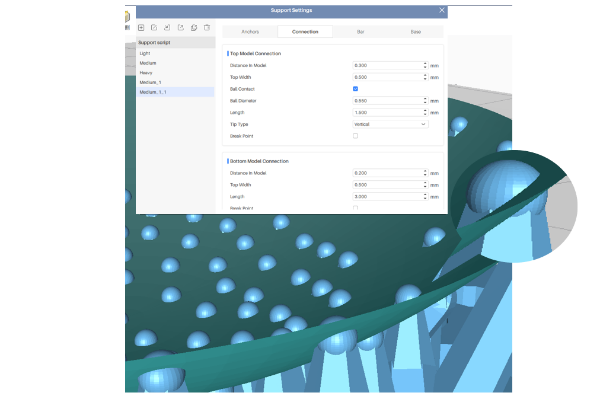

¶ 3) Default contact, with break point

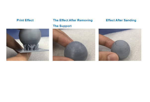
¶ 4) Ball contact, with break point

¶ 5) Test results
¶ ①Model Printing Success Rate
No "Break Point" > With "Break Point"
Printing without the "Break Point" feature is more stable. Using the "Break Point" feature may cause printing failure if the layer count is high or the model is heavy.
¶ ②Support Removal Convenience
With "Break Point"> No "Break Point"
¶ ③Model Surface Effect after Polishing
Ball contact + "Break Point" > Default contact + "Break Point" > Ball contact > Default contact
¶ ④Model Post-Processing Convenience
Ball contact + "Break Point" feature has the best effect.
If the model surface effect requirement is not high or no post-processing is desired, a smaller "Top Width" and "Distance In Model" can be selected to set the default contact shape points for support.
If a high-quality surface effect is required and easy post-processing is desired, the ball contact can be set with appropriate "Ball Diameter", "Distance In Model", "Top Width" parameter values, and with the "Break Point" feature.
¶ 5. Using Tools to Remove Support Structures
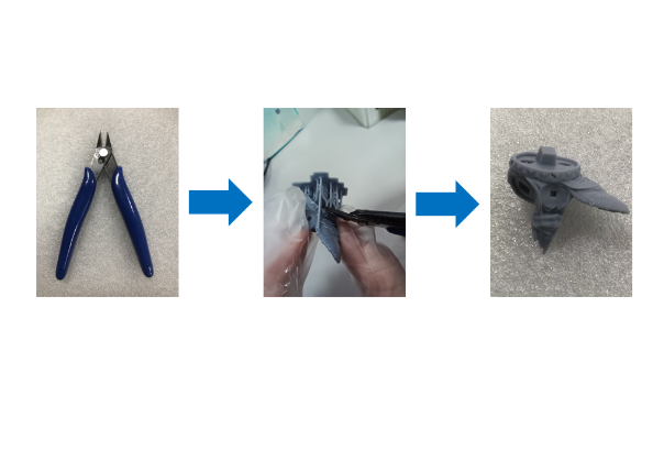
All support structure examples in this article are based on manual removal. However, if you have enough time and patience, you can try using tools to remove the support structures, such as using diagonal pliers to cut the model and support structures at their contact points.
Advantages: This method will not produce holes or protrusions, and you can achieve a good model surface effect without or with minimal sanding, filling or other post-processing.
Disadvantages: This method requires more time and effort.
